
Intelligent monitoring system used for vibrating screen

An intelligent monitoring system, vibrating screen technology, applied in general control systems, control/adjustment systems, filter screens, etc., can solve the problems of difficult installation, easily disturbed data, fatigue vibration of vibration springs, etc. The effect of increasing transmission distance and improving reliability

Pending Publication Date: 2019-01-29
SHANGHAI UNITRUSTON INTELLIGENT TECH CO LTD
View PDF0 Cites 2 Cited by
  • Summary
  • Abstract
  • Description
  • Claims
  • Application Information

AI Technical Summary

Problems solved by technology

[0005] 1. Due to the large size of the vibrating screen, the installation is difficult, and the maintenance cost after failure is high
[0006] 2. When the vibrating screen is running, the environment is relatively harsh, so the electrical control system of the vibrating screen and the control personnel are far away from the equipment, and personnel cannot monitor the equipment nearby
[0007] 3. Vibration motor temperature is too high to cause damage
[0008] 4. Vibration spring fatigue causes unbalanced vibration
[0009] 5. The deformation of the structural parts causes the unbalanced motion of the screen body
[0011] Although this method solves the problems during the operation of the vibrating screen, the installation of sensors will cause shortcomings in the process of data acquisition and transmission, as follows:
[0012] 1. The analog signal transmission distance of the sensor or transmitter is long, and it is easy to be interfered and cause inaccurate data
[0013] 2. With the increase of the usage of sensors, more and more wirings will increase the difficulty of equipment maintenance
[0014] 3. The sensor signal must pass through the control cabinet to be uploaded to the cloud platform, and the secondary data forwarding is prone to errors

Method used


Image

  • Intelligent monitoring system used for vibrating screen
  • Intelligent monitoring system used for vibrating screen
  • Intelligent monitoring system used for vibrating screen

Examples


Embodiment 1

[0039] An intelligent monitoring system for a vibrating screen, characterized in that: comprising

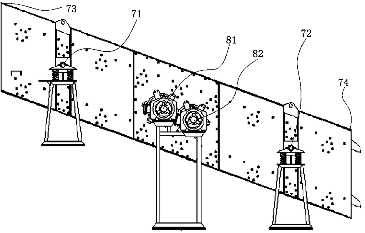
[0040] A number of vibration sensors are respectively arranged on the four corners of the screen box 1 of the vibrating screen and the damping spring 5 of the vibrating screen to monitor the vibration of the vibrating screen and the fatigue state of the damping spring 5; see image 3 , where the two vibration sensors 71, 72 are respectively arranged on the vibrating screen springs, the two vibration sensors 73 are respectively arranged on the two corners on the left side of the screen box; the two vibration sensors 74 are respectively arranged on the right side of the screen box 1 on the two corners of

[0041] A number of temperature sensors are respectively arranged on the driving motor 4 of the vibrating screen to monitor the bearing temperature of the driving motor 4, and give an early warning before the temperature reaches a dangerous value, which can completely avoid the d...


PUM


Abstract

The invention relates to the technical field of sensor measurement and processing, in particular to an intelligent monitoring system used for a vibrating screen. The intelligent monitoring system is characterized by comprising a plurality of vibration sensors which are arranged on four corners of a screen box of the vibrating screen and vibration reducing springs of the vibrating screen, and a plurality of temperature sensors arranged on a drive motor of the vibrating screen; the corresponding signal ends of an MCU processor are connected with the corresponding signal ends of the vibration sensors and the temperature sensors separately; the signal output ends of the vibration sensors and the temperature sensors are connected with a sensor field bus; the sensor field bus is further connected with a field control center processor; and the signal end of the field control center processor is further connected with an outer bus to achieve communication with a cloud service platform and a remote monitoring center. The intelligent monitoring system used for the vibrating screen has the following technical advantages that the problem of movement imbalance of the vibrating screen is solved,the fatigue state of the springs of the vibrating screen is monitored, and arrangement of wires of the system is greatly reduced.

Description

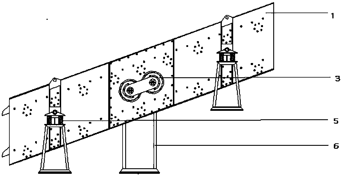
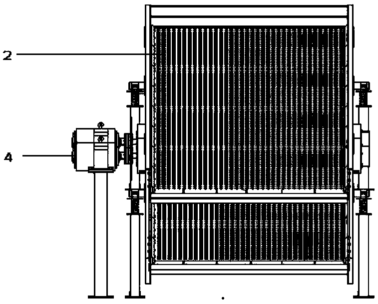
technical field [0001] The invention relates to the technical field of sensor measurement and processing, in particular to an intelligent monitoring system for vibrating screens. Background technique [0002] see figure 1 and figure 2 , Mining vibrating screen composition: Mining vibrating screen is composed of screen box 1, drive motor 4, damping spring 5, frame 6, screen 2, vibrator 3 and so on. The screen box 1 is composed of a screen frame, a liner and the like. The drive motor 4 adopts a motor with high performance and long life as the excitation source; the vibrator is composed of an eccentric block, and changing the weight of the eccentric block can change the vibration amplitude of the screen machine. [0003] The screen box 1 relies on two identical driving motors 4 to perform self-synchronous rotation in opposite directions, so that the entire screen box 1 supported on the damping spring 5 and the frame 6 vibrates in a straight line, and the material falls into...

Claims


Application Information

Patent Timeline
IPC IPC(8): B07B1/28G05B19/048
CPCG05B19/048B07B1/28
Inventor 赵文龙杨宁马娜张文霞汪艺
Owner SHANGHAI UNITRUSTON INTELLIGENT TECH CO LTD
Learn More