Air conditioner bottom shell for overhead vehicle

A vehicle air conditioner and overhead technology, which is applied to vehicle components, air handling equipment, heating/cooling equipment, etc., can solve the problems of low strength, poor strength of the integrated LFT bottom shell, and small area of ​​the integrated LFT bottom shell. , to achieve the effect of increasing the area, improving the load-bearing capacity and improving the structural strength

Active Publication Date: 2019-01-29
SONGZ AUTOMOBILE AIR CONDITIONING
View PDF12 Cites 1 Cited by
  • Summary
  • Abstract
  • Description
  • Claims
  • Application Information

AI Technical Summary

Problems solved by technology

Due to the limitation of production equipment, large-scale molding equipment (5,000 tons) can only mold structural parts with a projected area of ​​less than 4 square meters, and structural parts exceeding this area cannot be molded, so the air-conditioning bottom shell with a larger area cannot be molded. It is impossible to assemble larger air-conditioning components; on the other hand, the weight of the mainstream pure electric air conditioners on the market is about 250kg-400kg, and the load-bearing requirements for the air-conditioning bottom shell are relatively high, and the existing one-piece LFT bottom shell is not strong enough , cannot bear the weight
[0003] Therefore, there is an urgent need to design a top-mounted vehicle air-conditioning bottom case to solve the technical problems of the integrated LFT bottom case with small area and low strength in the above-mentioned prior art

Method used


Image

  • Air conditioner bottom shell for overhead vehicle
  • Air conditioner bottom shell for overhead vehicle
  • Air conditioner bottom shell for overhead vehicle

Examples


Embodiment Construction

[0030] The technical solutions of the present invention will be further described below in conjunction with the accompanying drawings and embodiments. It should be understood that the specific implementation manners described here are only used to explain the present invention, rather than to limit the present invention. In addition, it should be noted that, for the convenience of description, the accompanying drawings only show some but not all of the parts related to the present invention.

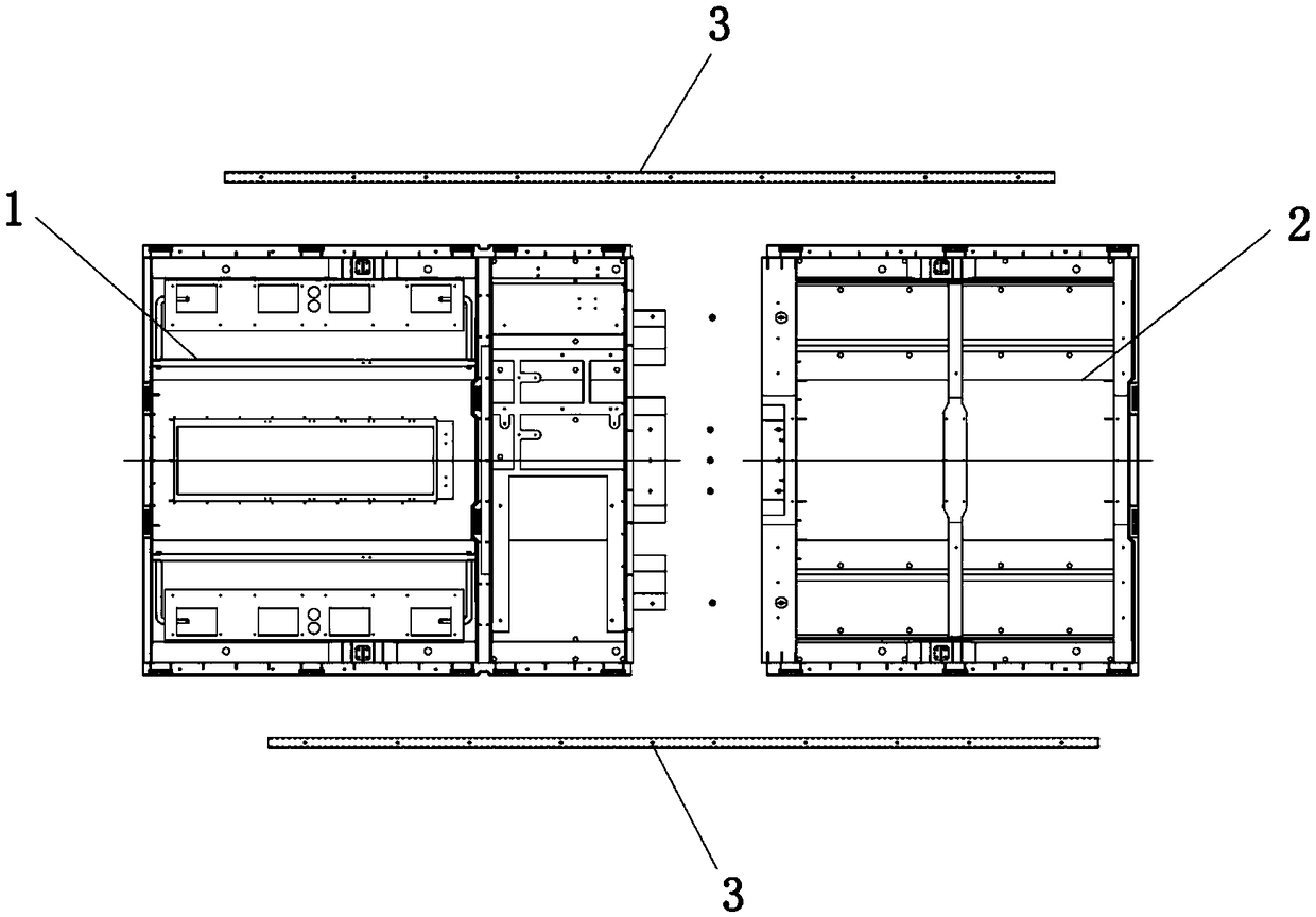
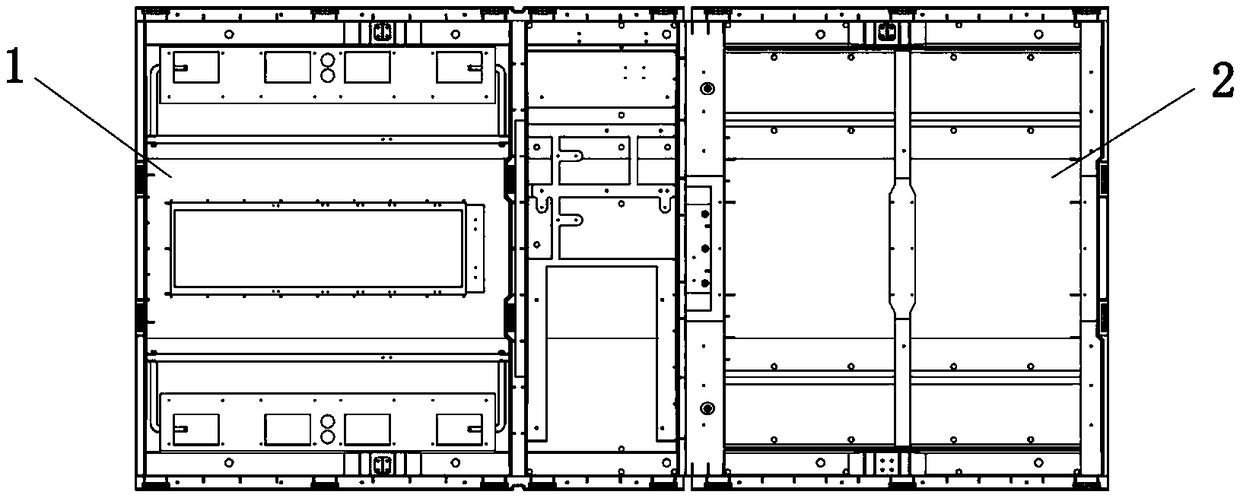
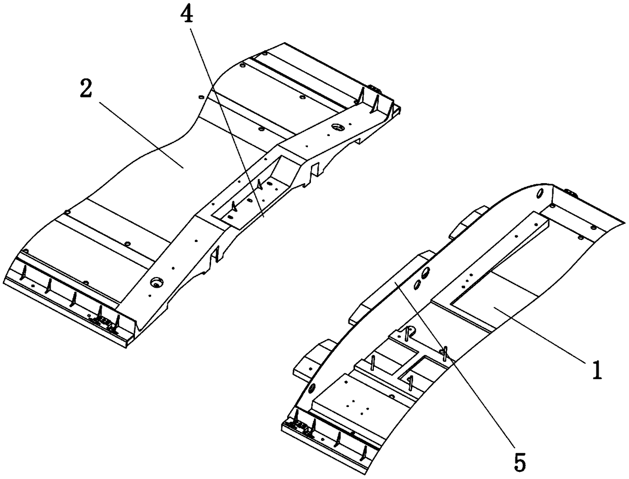
[0031] like figure 1 and figure 2 As shown, this embodiment provides a top-mounted vehicle air-conditioning bottom case, including a first bottom case 1, a second bottom case 2 and a structural beam 3, the first bottom case 1 is used to assemble an evaporator and a compressor, and the second bottom case The second bottom case 2 is used for assembling the condenser, the second bottom case 2 is detachably connected with the first bottom case 1 , and the structural beam 3 is arranged thr...


PUM


Abstract

The invention relates to the technical field of vehicle air conditioners and discloses an air conditioner bottom shell for an overhead vehicle. The air conditioner bottom shell for the overhead vehicle comprises a first bottom shell, a second bottom shell and a structural beam; the first bottom shell is used for assembling an evaporator and a compressor; the second bottom shell is used for assembling a condenser; the second bottom shell is detachably connected with the first bottom shell; and the structural beam is arranged at the bottom of the first bottom shell and the bottom of the second bottom shell in a through manner. The invention discloses a detachably connected bottom shell assembly; compared with an integrally molded structure, a separated structure has the advantages that the area of the bottom shell can be effectively increased so that the separated structure is suitable for larger vehicles, and hoisting, transferring and mounting of the air conditioner and the assemblingof a large-sized heat exchanger can be satisfied. As the structural beam is arranged at the bottom of the bottom shell, the integral structural strength of the bottom shell can be effectively improvedso that the load bearing capacity of the bottom shell is improved; a greater heat exchanging core body and electric compressors with multiple brands can be assembled in the shell so that heat exchanging amount demands of 10-14 m pure electric vehicles such as buses, tourist buses and airport shuttle buses are met.

Description

technical field [0001] The invention relates to the technical field of vehicle air conditioners, in particular to a top-mounted vehicle air conditioner bottom case. Background technique [0002] At present, most passenger cars on the market are equipped with roof-mounted air conditioners, and the roof-mounted air conditioners use LFT (Long Fiber reinforced thermoplastics, Long Fiber reinforced Thermoplastics) molded bottom shells, which are all of one-piece structure. Due to the limitation of production equipment, large-scale molding equipment (5,000 tons) can only mold structural parts with a projected area of ​​less than 4 square meters, and structural parts exceeding this area cannot be molded, so the air-conditioning bottom shell with a larger area cannot be molded. It is impossible to assemble larger air-conditioning components; on the other hand, the weight of the mainstream pure electric air conditioners on the market is about 250kg-400kg, and the load-bearing require...

Claims


Application Information

Patent Timeline
Patent Type & Authority Applications(China)
IPC IPC(8): B60H1/00
CPCB60H1/00392B60H1/00514B60H1/00528
Inventor 黄萍杨涛黄定英
Owner SONGZ AUTOMOBILE AIR CONDITIONING
Why Eureka
Try Eureka