An automatic anti-glare automotive electronic rearview mirror
A technology for automotive electronics and rearview mirrors, applied in the field of automotive rearview mirrors, can solve problems such as difficult anti-glare, achieve good anti-glare effect, wide application range, and reduced response time.
- Summary
- Abstract
- Description
- Claims
- Application Information
AI Technical Summary
Problems solved by technology
Method used
Image
Examples
Embodiment 1
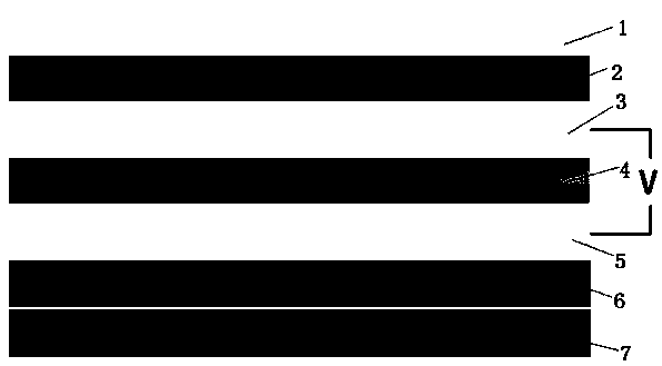
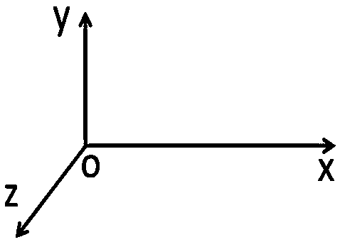
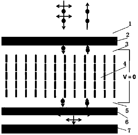
[0044] An automatic anti-glare automotive electronic rearview mirror, comprising a housing and a mirror structure arranged on the housing, the mirror structure is as figure 1 Shown: including a glass cover 1, a front glass substrate 3, a rear glass substrate 5, a front polarizer 2, a rear reflective polarizer 6, and a light-absorbing layer 7, forming a sandwich structure between the front glass substrate 3 and the rear glass substrate 5 The sandwich structure is filled with a liquid crystal layer 4, the front polarizer 2 and the rear reflective polarizer 6 are respectively arranged on the outside of the front glass substrate 3 and the rear glass substrate 5, and the glass cover plate 1 is arranged on the outside of the front polarizer 2, The light-absorbing layer 7 is arranged on the outside of the rear reflective polarizer 6; on the opposite sides of the front glass substrate 3 and the rear glass substrate 5, a liquid crystal alignment layer is arranged, and the liquid crystal...
Embodiment 2
[0057] The difference between this embodiment and Embodiment 1 lies in that the alignment modes of the liquid crystal molecules in the liquid crystal layer 4 are different.
[0058] In this embodiment, the alignment mode of the liquid crystal molecules of the liquid crystal layer 4 includes a horizontal alignment mode, and the horizontal alignment mode refers to that in the initial state, the positive liquid crystal molecules in the liquid crystal molecules of the liquid crystal layer 4 are all nearly parallel to the front glass substrate 3 and the rear glass substrate 5 are arranged, that is, the negative liquid crystal molecules in the liquid crystal molecules are arranged at an angle of 0.5 to 2 degrees or -0.5 to -2 degrees with the front glass substrate 3 and the rear glass substrate 5 . Under the action of the liquid crystal alignment layers of the front glass substrate 3 and the rear glass substrate 5, the projection directions of the positive liquid crystal molecules on...
Embodiment 3
[0064] The difference between this embodiment and Embodiment 1 lies in that the alignment modes of the liquid crystal molecules in the liquid crystal layer 4 are different.
[0065] In this embodiment, the alignment mode of the liquid crystal molecules of the liquid crystal layer 4 includes a conventional twisted orientation mode, and the conventional twisted orientation mode refers to that in the initial state, the positive liquid crystal molecules in the liquid crystal molecules of the liquid crystal layer 4 are on the front glass substrate 3 90 degree or -90 degree twisted arrangement with rear glass substrate 5 . The projection of the positive liquid crystal molecules on the plane of the front glass substrate 3 forms an angle of 0 degree, 90 degree or -90 degree with the front polarizer 2 . In this mode, the optical path difference range of the liquid crystal layer 4 is 375nm≤∆nd≤575nm or 900nm≤∆nd≤1200nm. In this embodiment, the central value of the optical path differen...
PUM
 Abstract
Description
Claims
Application Information
 - R&D
- Intellectual Property
- Life Sciences
- Materials
- Tech Scout
- Unparalleled Data Quality
- Higher Quality Content
- 60% Fewer Hallucinations
Browse by: Latest US Patents, China's latest patents, Technical Efficacy Thesaurus, Application Domain, Technology Topic, Popular Technical Reports.
© 2025 PatSnap. All rights reserved.Legal|Privacy policy|Modern Slavery Act Transparency Statement|Sitemap|About US| Contact US: help@patsnap.com


