Clutch and demagnetizing slide motor using same

A clutch and demagnetization technology, applied in clutches, magnetic drive clutches, non-mechanical drive clutches, etc., can solve the problems of shortening the service life of the motor, low direct drive speed, short sliding distance, etc., to increase the sliding distance and eccentric adaptability. Strong, weight-saving effect

Pending Publication Date: 2019-01-29
常州市武进金顺机电有限公司
View PDF0 Cites 0 Cited by
  • Summary
  • Abstract
  • Description
  • Claims
  • Application Information

AI Technical Summary

Problems solved by technology

[0002] In the prior art, electric bicycle motors are divided into two categories: one is a high-speed permanent magnet DC motor with brushes driven through gear transmission deceleration; the other is a low-speed permanent magnet DC motor that directly drives a low rotating speed. There are two types of permanent magnet DC motors with brushes and permanent magnet DC motors without brushes. The existing electric bicycle motors use permanent magnet motors. Although it has the advantages of high efficiency and small size, because its magnetic poles are all The permanent magnet material is used, which has a strong magnetic field. When the power is cut off, the internal winding of the motor cuts the magnetic lines of force to generate resistance, resulting in a short sliding distance, especially when the battery is not powered. Riding is more laborious. Therefore, when riding an electric bicycle, the motor needs Continuous operation, so the power consumption is large, the motor heats up, and the service life of the motor is shortened

Method used


Image

  • Clutch and demagnetizing slide motor using same
  • Clutch and demagnetizing slide motor using same
  • Clutch and demagnetizing slide motor using same

Examples


Embodiment Construction

[0018] The present invention will be described in further detail below in conjunction with the accompanying drawings and specific embodiments.

[0019] In the present invention, terms such as "installation", "connection", "connection" and "fixation" should be interpreted in a broad sense, for example, it can be a fixed connection or a detachable connection, unless otherwise clearly specified and limited. , or integrated; it can be mechanically connected or electrically connected; it can be directly connected or indirectly connected through an intermediary, and it can be the internal communication of two components or the interaction relationship between two components. Those of ordinary skill in the art can understand the specific meanings of the above terms in the present invention according to specific situations.

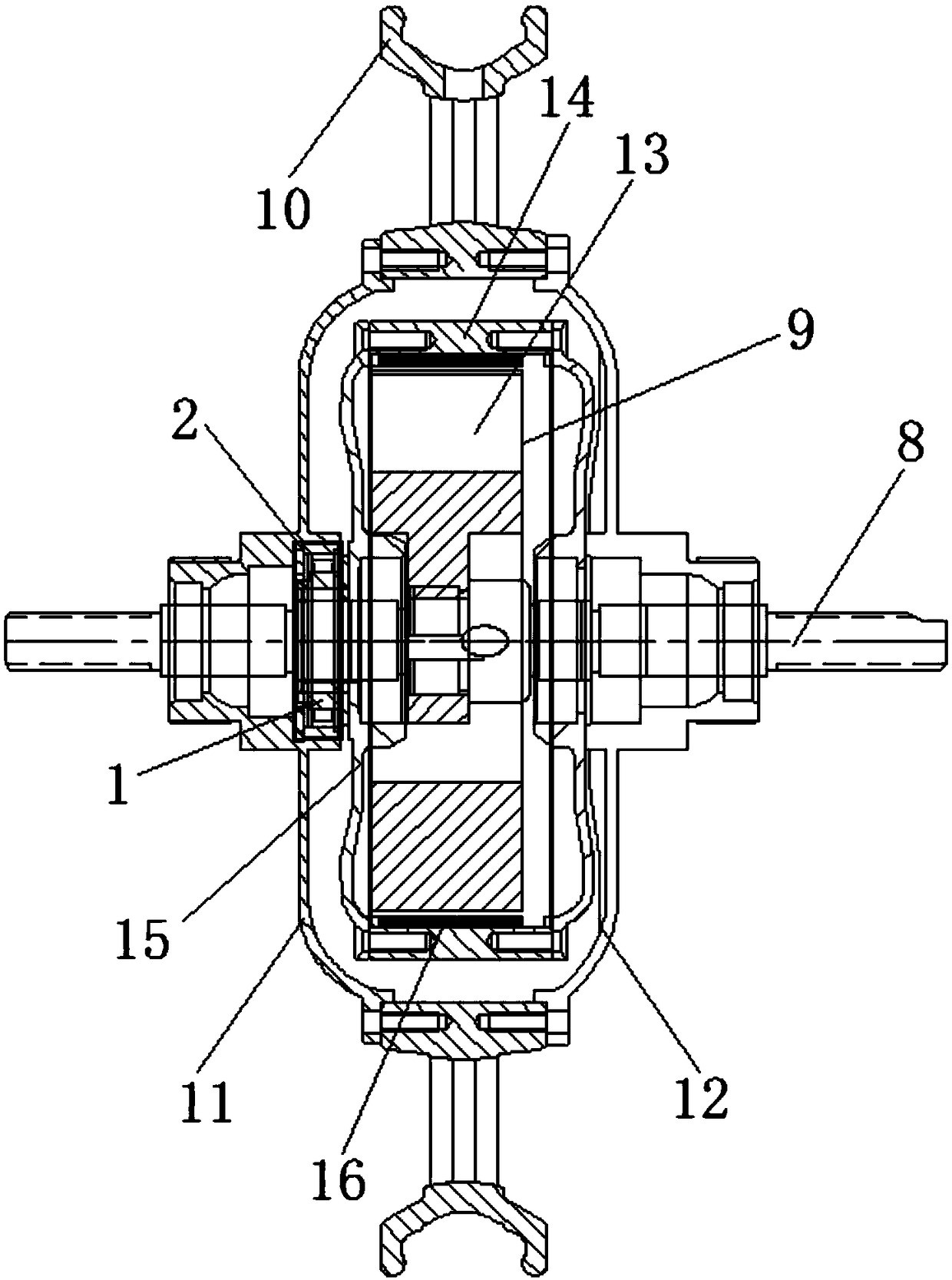
[0020] Such as figure 1 As shown, the present embodiment provides a clutch for a demagnetized gliding motor. The demagnetized gliding motor includes a motor sha...


PUM


Abstract

The invention belongs to the technical field of drive equipment, and relates to a clutch. The clutch comprises an inner ring and an outer ring, wherein the inner ring is arranged in the outer ring; anannular cavity is formed between the inner ring and the outer ring; a wedge block mechanism is arranged in the annular cavity; the wedge block mechanism comprises a wedge block support seat and wedgeblock assemblies; a plurality of installation grooves are uniformly distributed in the wedge block support seat; the wedge block assemblies are arranged in the plurality of installation grooves whichare uniformly distributed at intervals separately; an elastic pressure ring is arranged at the outer side of each wedge block assembly; and the wedge block assemblies are tightly clamped onto the inner ring under the action of the elastic pressure rings. According to the clutch, through the design of an inclined arc surface at one end making contact with the inner ring, of each wedge block assembly, and the design of the elastic pressure ring at one end away from the corresponding inclined arc surface, of each wedge block assembly, the problems of torque decline, clamping stagnation and the like caused due to the eccentricity of an existing clutch on an inner ring and an outer ring, are solved; and the clutch has the advantages of being simple in manufacturing process, reliable in working, large in bearing torque, high in eccentric adaptability, long in service life and the like.

Description

technical field [0001] The invention belongs to the technical field of drive equipment, and in particular relates to a clutch and a demagnetized sliding motor using the clutch. Background technique [0002] In the prior art, electric bicycle motors are divided into two categories: one is a high-speed permanent magnet DC motor with brushes driven through gear transmission deceleration; the other is a low-speed permanent magnet DC motor that directly drives a low rotating speed. There are two types of permanent magnet DC motors with brushes and permanent magnet DC motors without brushes. The existing electric bicycle motors use permanent magnet motors. Although it has the advantages of high efficiency and small size, because its magnetic poles are all The permanent magnet material is used, which has a strong magnetic field. When the power is cut off, the internal winding of the motor cuts the magnetic lines of force to generate resistance, resulting in a short sliding distance...

Claims


Application Information

Patent Timeline
Patent Type & Authority Applications(China)
IPC IPC(8): F16D27/10F16D27/14F16D27/108H02K7/10
CPCF16D27/10F16D27/108F16D27/14H02K7/10
Inventor 邵亚良孙林
Owner 常州市武进金顺机电有限公司
Why Eureka
Try Eureka