Adjustable three-dimensional loading test system suitable for steel concrete components with different sizes and shapes

A three-dimensional loading and testing system technology, applied in the direction of applying stable tension/pressure to test the strength of materials, instruments, measuring devices, etc., can solve the problems of poor versatility of testing devices, inconvenient installation and use, and poor versatility.

Active Publication Date: 2019-01-29
SHANDONG UNIV
View PDF10 Cites 1 Cited by
  • Summary
  • Abstract
  • Description
  • Claims
  • Application Information

AI Technical Summary

Problems solved by technology

[0003] Chinese patent ZL201010546650.8 invented a fatigue loading durability test device for steel concrete components. It is more suitable for plate-type reinforced concrete components, and the size cannot be adjusted, so the versatility is poor
[0008] 1) The test device has poor versatility, and the position of the loading frame and the position of the loading cylinder cannot be adjusted arbitrarily according to the shape and size of the steel concrete member;
[0009] 2) The structure of the test device is not compact, the loading space and loading tonnage are small, and the loading test of large-size, large-tonnage, and high-strength steel concrete components cannot be carried out;
[0010] 3) The loading test device cannot achieve self-balancing, and the loading frame cannot be automatically controlled to move and lock. It is inconvenient to install and use, and the flexibility is poor

Method used


Image

  • Adjustable three-dimensional loading test system suitable for steel concrete components with different sizes and shapes
  • Adjustable three-dimensional loading test system suitable for steel concrete components with different sizes and shapes
  • Adjustable three-dimensional loading test system suitable for steel concrete components with different sizes and shapes

Examples


Embodiment Construction

[0048] It should be pointed out that the following detailed description is exemplary and intended to provide further explanation to the present application. Unless defined otherwise, all technical and scientific terms used herein have the same meaning as commonly understood by one of ordinary skill in the art to which this application belongs.

[0049] It should be noted that the terminology used here is only for describing specific implementations, and is not intended to limit the exemplary implementations according to the present application. As used herein, unless the context clearly dictates otherwise, the singular is intended to include the plural, and it should also be understood that when the terms "comprising" and / or "comprising" are used in this specification, they mean There are features, steps, operations, means, components and / or combinations thereof;

[0050] For the convenience of description, if the words "up", "down", "left" and "right" appear in the present i...


PUM


Abstract

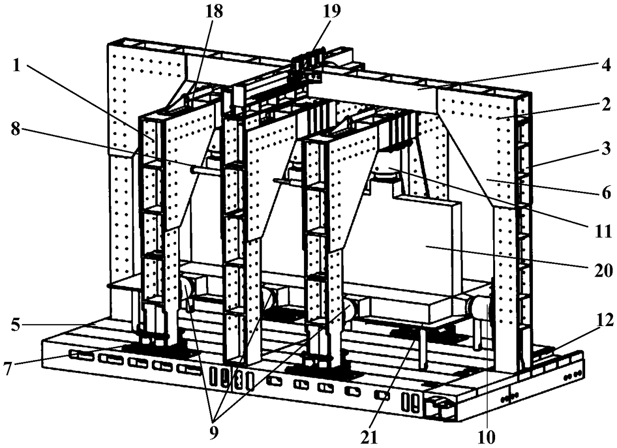
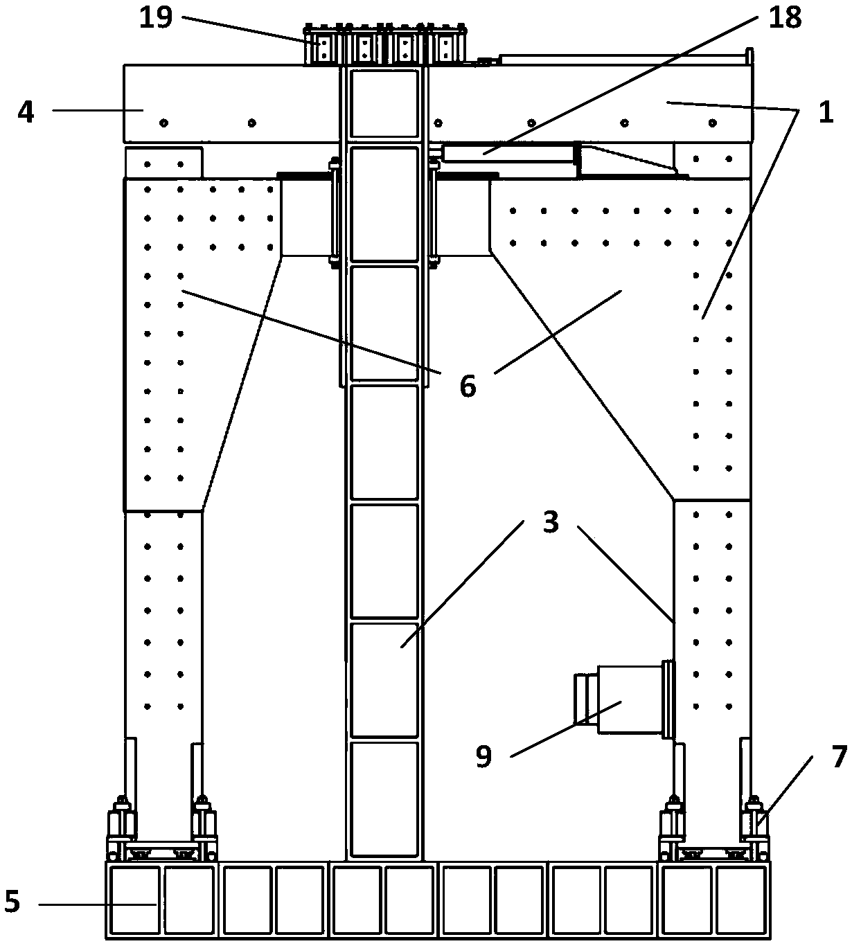
The invention relates to a combined adjustable three-dimensional loading test system suitable for steel concrete components with different sizes and shapes. The combined adjustable three-dimensional loading test system comprises an assembly type base. The assembly type base is provided with a concentric-square-shaped structure I which can move in the left-right direction of the assembly type base,three concentric-square-shaped structures II are arranged inside the concentric-square-shaped structure I, the concentric-square-shaped structure II located in the middle is fixed, and the concentric-square-shaped structures II located on the two sides are driven by pushing cylinders to move in the front-rear direction of the assembly type base. A space enclosed by the three concentric-square-shaped structures II is internally provided with a lifting test platform, and the concentric-square-shaped structure I is provided with a rear loading cylinder for loading the rear part of the steel concrete components, and the concentric-square-shaped structures II are provided with side part loading cylinders for loading the side parts of the steel concrete components and upper part loading cylinders for loading the tops of the steel concrete components; and the loading cylinders are pushed and fixed by pushing and fixing devices.

Description

technical field [0001] The invention relates to a combined adjustable three-dimensional loading test system applicable to steel concrete members of different sizes and shapes. technical background [0002] At present, a large number of steel concrete components are used in various projects. In order to meet the needs of different projects, it is necessary to make steel concrete components of different sizes and shapes; in order to ensure the quality and safety of the project, the physical and mechanical parameters of the steel concrete components need to be measured in detail. Reinforced concrete members are required for loading tests. Since steel concrete components have the characteristics of variable size and shape, uncertain loading position, and relatively large yield and failure loads, the loading test of steel concrete components must have large tonnage, high strength, flexible and adjustable loading position, and be suitable for various The shape of the component an...

Claims


Application Information

Patent Timeline
IPC IPC(8): G01N3/10G01N3/04
CPCG01N3/04G01N3/10G01N2203/0048
Inventor 王汉鹏王伟李术才张强勇刘众众章冲马正卫薛阳
Owner SHANDONG UNIV
Why Eureka
Try Eureka