Display device and driving method of display device

A technology for a display device and a driving circuit, which is applied to identification devices, static indicators, optics, etc., can solve the problems of the overall thickness of naked-eye 3D display devices, which is unfavorable for thin and light design, and achieves advantages of thin and light design and low power consumption. , the effect of reducing the overall thickness

Inactive Publication Date: 2019-01-29
SOUTH UNIVERSITY OF SCIENCE AND TECHNOLOGY OF CHINA
View PDF17 Cites 5 Cited by
  • Summary
  • Abstract
  • Description
  • Claims
  • Application Information

AI Technical Summary

Problems solved by technology

[0003] At present, the traditional naked-eye 3D display device is usually formed based on a liquid crystal display device. The liquid crystal display device usually includes a backlight module, a lower polarizer, a liquid crystal cell, an upper polarizer, and a color filter film. In addition, the naked-eye 3D display device also includes light adjustment. system, the light adjustment system is located on the light-emitting side of the liquid crystal display device. The structural design of the above-mentioned multi-layer film layer results in a thicker overall thickness of the naked-eye 3D display device, which is not conducive to its light and thin design.
In addition, in the traditional naked-eye 3D display device, the light adjustment system can only adjust the 3D display screen to a fixed position, that is, the viewer can only watch the 3D image at a fixed position

Method used


Image

  • Display device and driving method of display device
  • Display device and driving method of display device
  • Display device and driving method of display device

Examples


Embodiment Construction

[0047] The present invention will be further described in detail below in conjunction with the accompanying drawings and embodiments. It should be understood that the specific embodiments described here are only used to explain the present invention, but not to limit the present invention. In addition, it should be noted that, for the convenience of description, only some structures related to the present invention are shown in the drawings but not all structures.

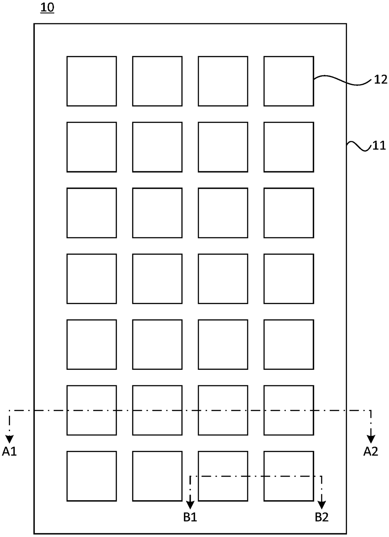
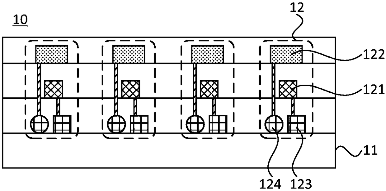
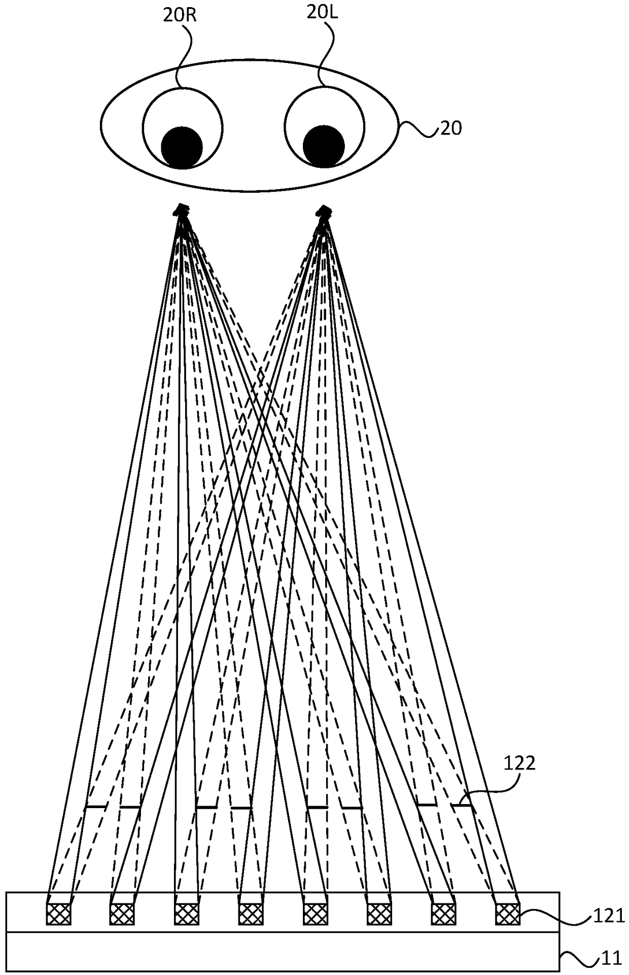
[0048] figure 1 is a schematic plan view of a display device provided by an embodiment of the present invention, figure 2 is along figure 1 The schematic diagram of the cross-sectional structure of A1-A2, image 3 It is a schematic diagram of a 3D imaging principle of a display device provided by an embodiment of the present invention. refer to figure 1 , figure 2with image 3 , the display device 10 includes: a base substrate 11; a plurality of pixel units 12 arranged in an array arranged on one side of t...


PUM


Abstract

The invention discloses a display device. The display device comprises a substrate, and a plurality of pixel units arranged in an array on one side of the substrate; wherein each pixel unit comprisesa MicroLED, a light adjustment module, a first driving circuit module and a second driving circuit module; the light adjustment module is located on one side of the MicroLED away from the substrate, and the first driving circuit module and the second driving circuit module are both located on one side of the MicroLED close to the substrate; the MicroLED is electrically connected with the first driving circuit module, and the light adjustment module is electrically connected with the second driving circuit module; and the light adjustment module is used for adjusting a light emission directionof the light emitted from the MicroLED under the driving of the second driving circuit module, so that the light corresponding to a left eye image enters a left eye of a user, and the light corresponding to a left eye image enters a right eye of the user, and adjusting a 3D viewing position of the display device. By adoption of the technical solution of the invention, the overall thickness of thedisplay device can be reduced, which is advantageous for thin and light design; and the3D viewing position of the display device can be adjusted at the same time.

Description

technical field [0001] Embodiments of the present invention relate to the field of display technologies, and in particular, to a display device and a driving method for the display device. Background technique [0002] With the development of 3D (three-dimensional, three-dimensional graphics) display technology, there is a naked-eye 3D display device in the prior art, that is, a 3D display device in which a user can observe a 3D display effect with naked eyes without wearing auxiliary glasses. [0003] At present, the traditional naked-eye 3D display device is usually formed based on a liquid crystal display device. The liquid crystal display device usually includes a backlight module, a lower polarizer, a liquid crystal cell, an upper polarizer, and a color filter film. In addition, the naked-eye 3D display device also includes light adjustment. system, the light adjustment system is located on the light-emitting side of the liquid crystal display device, and the structural...

Claims


Application Information

Patent Timeline
Patent Type & Authority Applications(China)
IPC IPC(8): G02B27/22G09F9/33G09G3/32
CPCG09F9/33G09G3/32G02B30/27
Inventor 孙小卫王恺周子明徐冰
Owner SOUTH UNIVERSITY OF SCIENCE AND TECHNOLOGY OF CHINA
Why Eureka
Try Eureka