
Parameter configuration method and electronic equipment

A parameter configuration method and technology of electronic equipment, applied in the computer field, can solve problems such as interrupt mutual interference, too many or too few interrupt queues, and inability to make full use of the computing power of electronic equipment, so as to achieve the effect of ensuring balanced distribution and realizing reasonable distribution

Active Publication Date: 2019-01-29
CHINANETCENT TECH
View PDF13 Cites 5 Cited by
  • Summary
  • Abstract
  • Description
  • Claims
  • Application Information

AI Technical Summary

Problems solved by technology

However, when the network card driver is initialized and loaded, it often directly uses the number of interrupt queues configured by default, and ignores the cooperation with the multi-core processor architecture of the machine (such as non-uniform memory access architecture and hyper-threading technology), which is prone to interrupt queue numbers. Too much or too little, too much may cause mutual interference of such interruptions, too little and the computing power of each component of the electronic device cannot be fully utilized
Moreover, if the physical CPU core and the logical CPU core are confused, multiple interrupts of the network card may be bound to the same physical CPU core (for example, the interrupts are respectively bound to two logical cores, but this logical core belongs to On the same physical core), that is to say, it destroys the concurrent communication mode between the multi-core processor and the multi-queue network card. The interrupt events processed by the same physical CPU core will be too many, resulting in increased delay and decreased processing performance, which will lead to The packet loss rate of the network card increases greatly, and the bandwidth of the network card decreases in network performance.

Method used


Image

  • Parameter configuration method and electronic equipment
  • Parameter configuration method and electronic equipment
  • Parameter configuration method and electronic equipment

Examples


Embodiment Construction

[0021] In order to make the purpose, technical solutions and advantages of the embodiments of the present invention more clear, the following will describe each embodiment of the present invention in detail with reference to the accompanying drawings. However, those of ordinary skill in the art can understand that, in each implementation manner of the present invention, many technical details are provided for readers to better understand the present application. However, even without these technical details and various changes and modifications based on the following implementation modes, the technical solution claimed in this application can also be realized.

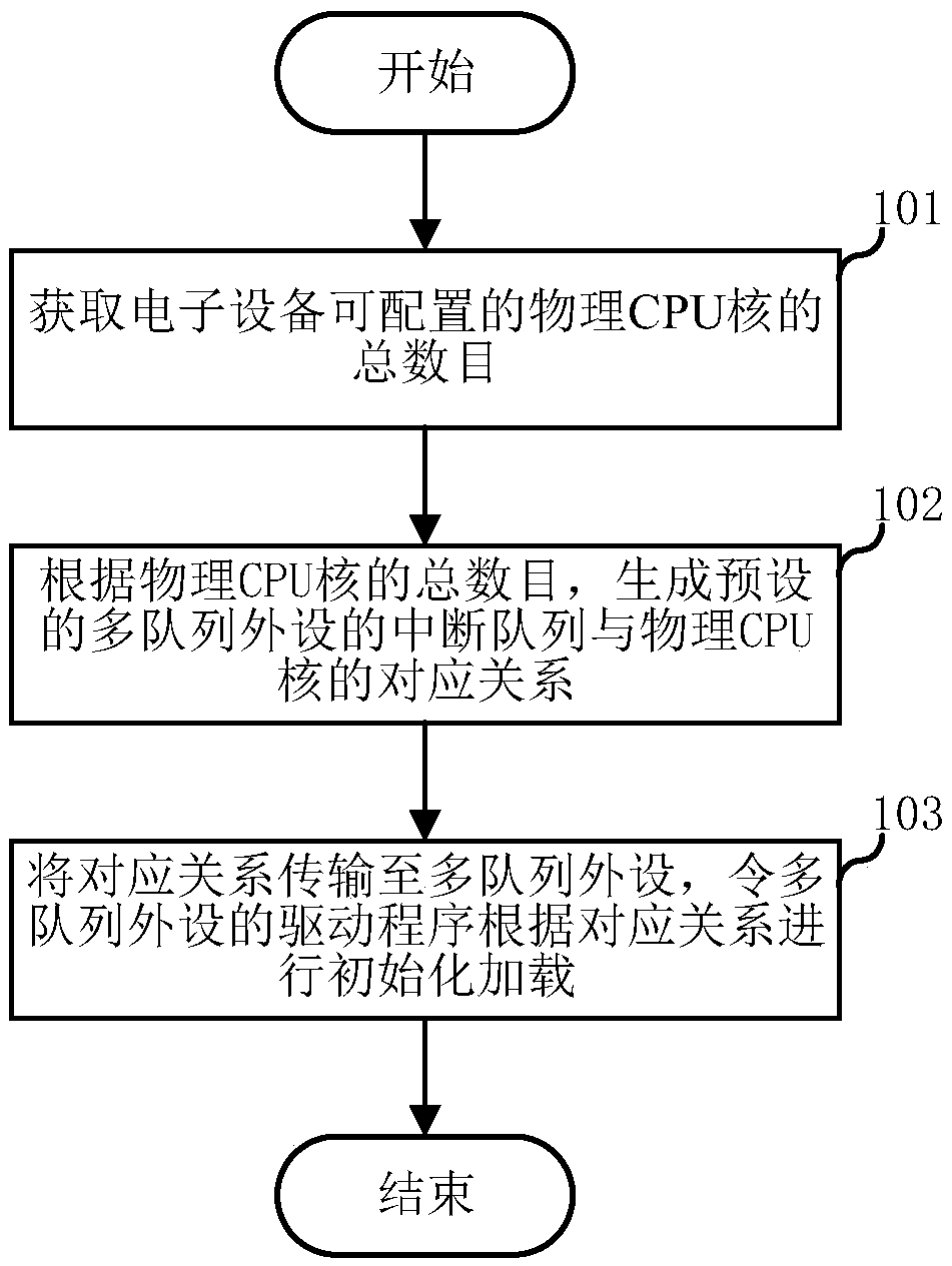
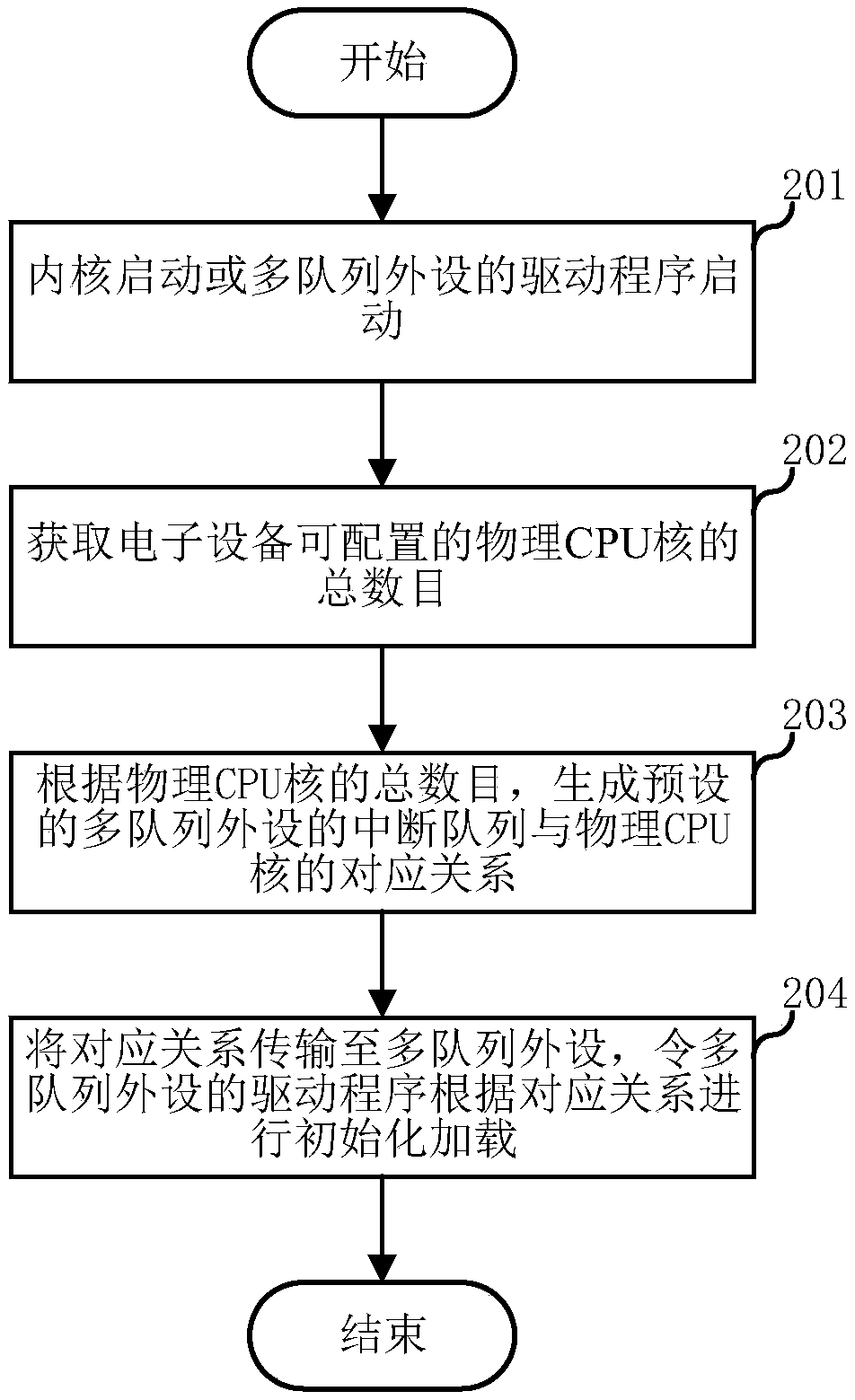
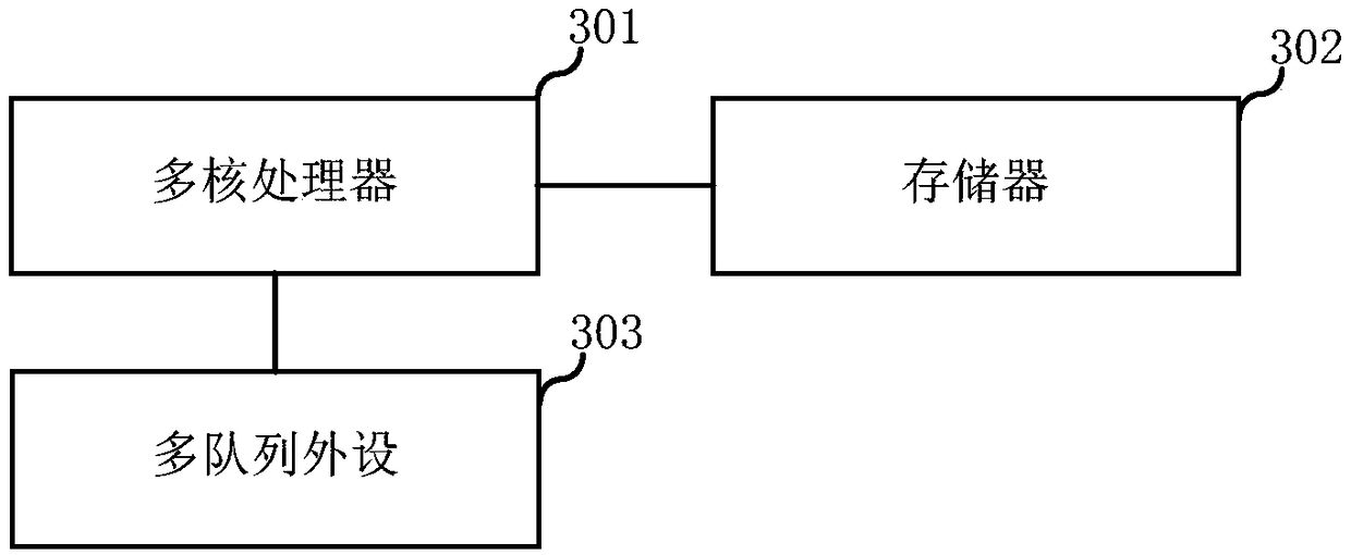
[0022] The first embodiment of the present invention relates to a parameter configuration method, the specific process is as follows figure 1 shown. The parameter configuration method in this embodiment is applied to an electronic device including multiple physical CPU cores, and the electronic device has multiple per...


PUM


Abstract

The embodiment of the invention relates to the computer technical field, and discloses a parameter configuration method and an electronic device. In an embodiment of the present invention, the parameter configuration method is applied to an electronic device including a plurality of physical CPU cores. The method comprises the following steps: acquiring a total number of configurable physical CPUcores of the electronic device; according to the total number of physical CPU cores, the corresponding relationship between the preset multi-queue peripheral interrupt queues and the physical CPU cores is generated. Where each physical CPU core pair should have at least one interrupt queue and at most two pairs of interrupt queues. As such, that correspondence is transmit to a multi-queue peripheral. The driver of the multi-queue peripheral device is initialized and loaded according to the corresponding relationship, so that the reasonable allocation of the interrupt queue can be carried out as far as possible, the situation that multiple interrupt queues are bound to the same physical CPU core is avoided, and the utilization ratio of the computing power of the electronic device is improved.

Description

technical field [0001] The embodiments of the present invention relate to the field of computer technology, in particular to a parameter configuration method and electronic equipment. Background technique [0002] With the increasing demand for Internet services such as computing processing and communication, many electronic devices are equipped with multi-core processors to achieve high performance. At the same time, more and more electronic devices have enabled CPU hyper-threading technology to achieve logical CPU Double the number of physical CPU cores in order to increase the computing power of a single machine. [0003] At present, in order to meet the increasing demand for high-speed network processing, electronic devices are usually equipped with Gigabit, 10 Gigabit or even higher-performance network adapters (commonly known as "network cards"). However, the inventors of the present invention found that: [0004] The simple superposition of high-performance devices ...

Claims


Application Information

Patent Timeline
IPC IPC(8): G06F9/50G06F9/48
CPCG06F9/4812G06F9/5027
Inventor 罗裕陈文生
Owner CHINANETCENT TECH
Learn More