Spray molding equipment

An injection molding and equipment technology, applied in the direction of injection devices, etc., can solve the problems of increasing the power consumption of the device, increasing the time cost, and slowing the injection speed, and achieving the effects of improving efficiency, reducing power consumption and uniform injection.

Inactive Publication Date: 2019-02-01
余连平
View PDF0 Cites 10 Cited by
  • Summary
  • Abstract
  • Description
  • Claims
  • Application Information

AI Technical Summary

Problems solved by technology

[0002] The current injection molding device sprays the surface of the object to be injected by mixing liquid and inert gas through an atomizer, so that the injection efficiency is uniform and smooth. This method is widely used and popularized, but the current injection molding device uses the rotation and The object is sprayed all over the body. The s

Method used


Image

  • Spray molding equipment
  • Spray molding equipment
  • Spray molding equipment

Examples


Example Embodiment

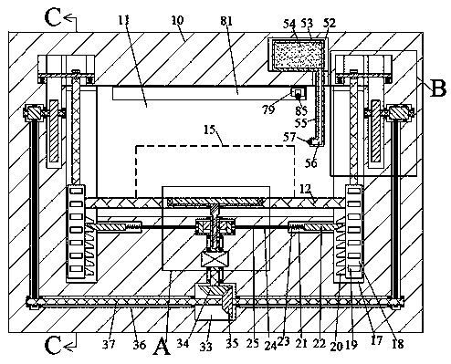
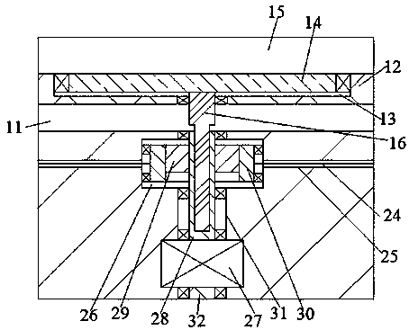
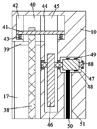
[0014] Combine below Figure 1-6 The present invention will be described in detail. For the convenience of description, the orientations mentioned below are now specified as follows: figure 1 The vertical, horizontal, front and rear directions of the projection relationship are the same.

[0015] Reference Figure 1-6 , An injection molding equipment according to an embodiment of the present invention includes a body 10 with an injection cavity 11 in the body 10, a support plate 12 in the injection cavity 11, and an opening in the support plate 12 The upward groove 13 is provided with a placement plate 14 rotating in the groove 13, on which the object to be sprayed 15 is placed, and the lower end of the placement plate 14 is fixedly provided with a spline connection with the lower end of the rotating device The spline shaft 16, the symmetrical opening of the spray cavity 11 is provided with the lifting grooves 17, the left and right ends of the support plate 12 respectively exte...


PUM


Abstract

The invention discloses spray molding equipment. The spray molding equipment comprises a machine body. The machine body is internally provided with an spray cavity. The spray cavity is internally provided with a supporting plate. The supporting plate is internally provided with a groove with an upward opening. A carrying plate is rotatably arranged in the groove. An article to be sprayed is placedon the carrying plate. The lower end face of the carrying plate is fixedly provided with a spline shaft in spline connection with a rotating device. Lifting grooves with opposite openings are formedin the spray cavity in bilateral symmetry in a communication mode. The spray molding equipment is simple in structure and convenient to operate, completes rotary spray through lifting components whilemaking the article to be sprayed to rise so that the whole body of the article to be sprayed can be sprayed comprehensively. A horizontal spraying device moves horizontally while conducting sprayingfront and back so as to achieve the uniform spraying effect; secondly, through comprehensive rotary spraying and horizontal spraying on the upper surface, the spraying time can be shortened, and the spraying molding efficiency of the spray molding equipment can be improved. The spray molding equipment is small in occupied area and convenient to operate and overhaul.

Description

technical field [0001] The invention relates to the technical field of injection molding, in particular to an injection molding equipment. Background technique [0002] The current injection molding device sprays the surface of the object to be injected by mixing liquid and inert gas through an atomizer, so that the injection efficiency is uniform and smooth. This method is widely used and promoted, but the current injection molding device uses the rotation and Objects are sprayed all over the body. The spraying speed of this device is slow and takes a long time, resulting in slow spraying efficiency and increasing time costs. Moreover, the work between various processes requires the use of multiple motors, which increases the power consumption of the device. Therefore, it is urgently needed. A safe, efficient and automated injection molding equipment. Contents of the invention [0003] The object of the present invention is to provide an injection molding equipment for o...

Claims


Application Information

Patent Timeline
IPC IPC(8): B05B13/02B05B13/04
CPCB05B13/0235B05B13/0442
Inventor 余连平
Owner 余连平
Why Eureka
Try Eureka