Push-pull tire energy recovery device

An energy recovery device, push-pull technology, applied in the direction of wheels, vehicle parts, transportation and packaging, etc., can solve the problem that the energy of automobile tires cannot be recovered, and achieve the effect of stable recovery

Active Publication Date: 2019-02-01
李钊河
View PDF4 Cites 0 Cited by
  • Summary
  • Abstract
  • Description
  • Claims
  • Application Information

AI Technical Summary

Problems solved by technology

[0003] In order to solve the above problems, the object of the present invention is to provide a push-pull tire energy recovery device to solve the problem that the energy consumed by the deformation of automobile tires cannot be recovered at present.

Method used


Image

  • Push-pull tire energy recovery device
  • Push-pull tire energy recovery device
  • Push-pull tire energy recovery device

Examples


Embodiment Construction

[0024] The specific implementation manners of the present invention will be further described in detail below in conjunction with the accompanying drawings and embodiments. The following examples are used to illustrate the present invention, but are not intended to limit the scope of the present invention.

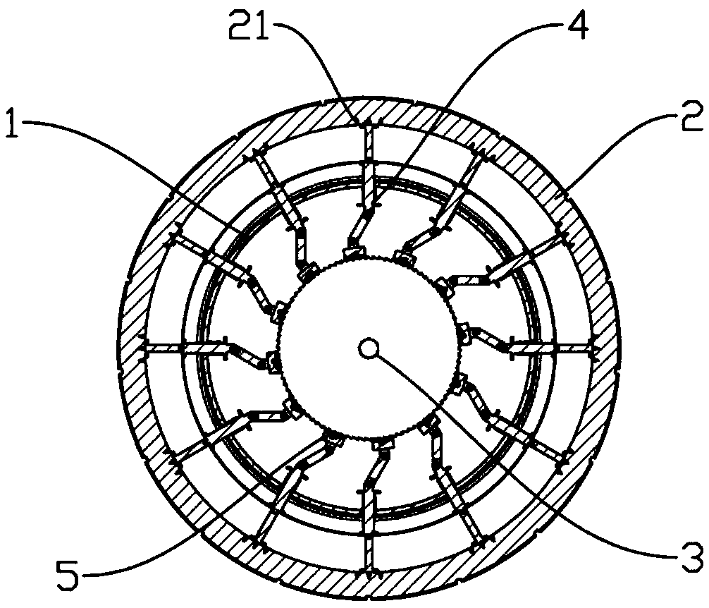
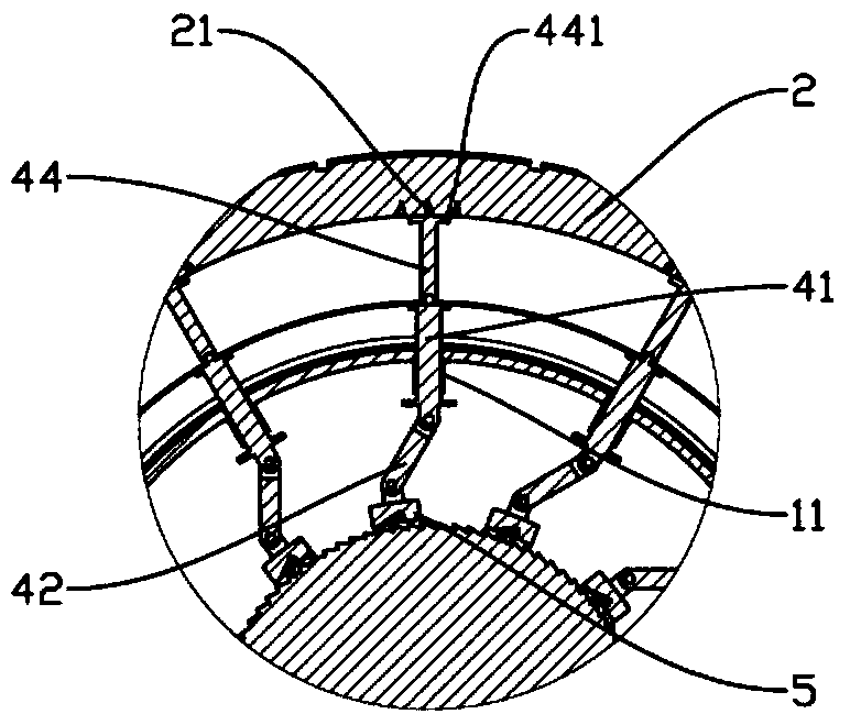
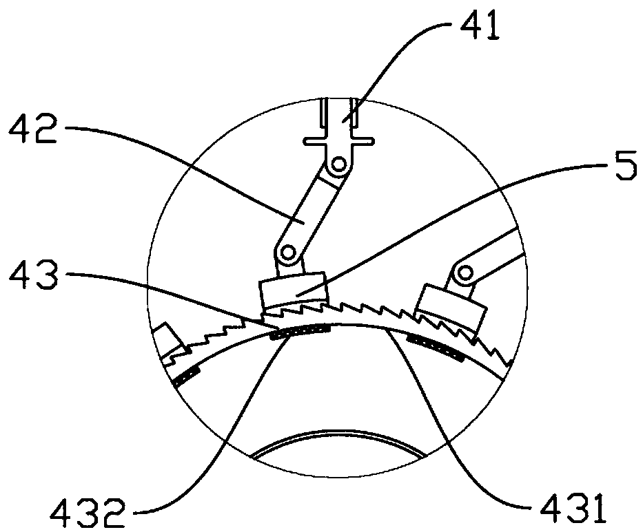
[0025] combine Figure 1 to Figure 6 As shown, the push-pull tire energy recovery device of the present invention is schematically shown, including a hub 1 , a tire 2 installed on the outer circumference of the hub 1 , an output shaft 3 and a plurality of energy-taking devices 4 . Such as figure 2 The energy harvesting device 4 includes a transmission rod 44, a first part 41 and a second part 42. The first part 41 is movably installed on the hub 1 and can slide radially along the hub 1. There are a plurality of guide cylinders 11, the center line of the guide cylinder 11 coincides with the radius line of the hub 1, and the first part 41 is movably installed in the guide...


PUM


Abstract

The invention relates to the field of energy recovery, in particular to a push-pull tire energy recovery device. A connecting rod assembly composed of a first component and a second component transmits the power of tire compression or rebound to an output shaft. A one-way clutch assembly is arranged between the movable end of the second component and the output shaft. The one-way clutch assembly ensures that the power transmitted by the first component and the second component can only push or pull the output shaft to rotate in the same direction, so that energy conversion devices such as generators can recover the energy of tire compression or rebound stably.

Description

technical field [0001] The invention relates to the field of energy recovery, in particular to a push-pull tire energy recovery device. Background technique [0002] Automobiles are the main means of transportation, and the global demand and ownership of automobiles is huge and continues to grow. The energy consumption and environmental protection problems caused by the driving of automobiles have become increasingly prominent, and energy conservation and emission reduction have become an important direction of automobile development. Energy recovery is one of the important means of energy saving and emission reduction. Car tires are deformed due to the gravity of the car, resulting in a large friction force between the tire and the road surface, resulting in a large reactive power loss of the car power, which increases energy consumption. Then, if the energy generated by the deformation of this tire can be recycled, it will greatly save the energy consumption of the car a...

Claims


Application Information

Patent Timeline
IPC IPC(8): B60B19/00F03G7/00
CPCF03G7/00B60B19/00
Inventor 李钊河李汯锜
Owner 李钊河
Why Eureka
Try Eureka