Water treatment system and power generation facility

a technology of water treatment system and power generation facility, applied in the direction of multi-stage water/sewage treatment, separation process, nature of treatment water, etc., can solve the problem of diminishing treatment capacity, and achieve the effect of stably recycling water and efficiently removing soluble silica

Inactive Publication Date: 2017-02-02
MITSUBISHI HEAVY IND ENG LTD
View PDF8 Cites 4 Cited by
  • Summary
  • Abstract
  • Description
  • Claims
  • Application Information

AI Technical Summary

Benefits of technology

[0030]According to the present invention, when reusing water to be treated containing at least salt content and silica such as cooling tower blowdown water from a cooling tower, for example, used at a plant facility or the like, it becomes possible to stably recycle water by efficiently removing soluble silica from the water to be treated.

Problems solved by technology

When scale is generated inside the apparatus for performing the desalination treatment described above, the treatment capacity is diminished.

Method used


Image

  • Water treatment system and power generation facility
  • Water treatment system and power generation facility
  • Water treatment system and power generation facility

Examples


embodiment 1

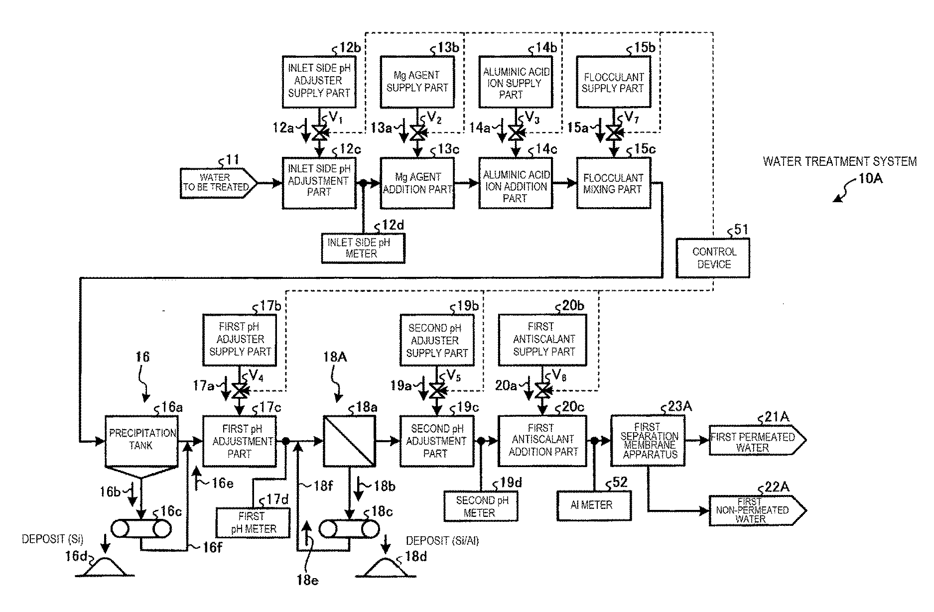
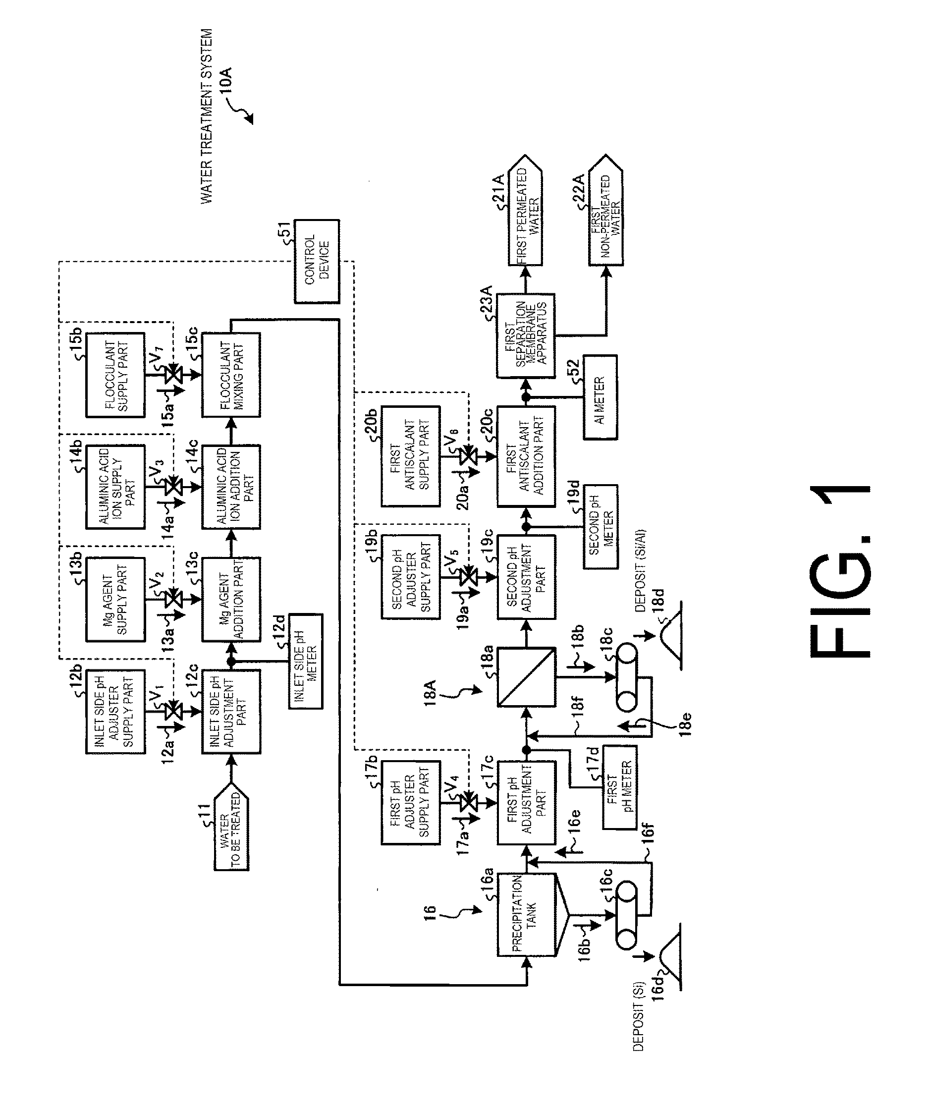
[0052]FIG. 1 is a schematic view of a water treatment system of Working Example 1. As illustrated in FIG. 1, a water treatment system 10A of this working example is equipped with: an aluminate ion addition part 14c for supplying and adding an aluminate ion additive 14a from an aluminate ion supply part 14b to water to be treated 11 containing at least salt content and silica; a first precipitation part 16 provided on the downstream side of the aluminate ion addition part 14c so as to precipitate and separate solid content in the water to be treated 11; a first pH adjustment part 17c provided on the downstream side of the first precipitation part 16 so as to adjust the pH to a first pH level (from pH to 7) which precipitates the residual aluminum in the water to be treated 11 by supplying a first pH adjusting agent 17a from a first pH adjusting agent supply part 17b to the water to be treated (supernatant water) 11 from the first precipitation part 16; a first solid / liquid separation...

embodiment 2

[0122]The water treatment system of Working Example 2 of the present invention will be described hereinafter with reference to the drawings.

[0123]FIG. 8 is a schematic view illustrating a water treatment system of Working Example 2. Note that members that are the same as those of the configuration of the water treatment system of Working Example 1 are labeled with the same symbols, and descriptions thereof are omitted.

[0124]As illustrated in FIG. 8, the water treatment system 10C of this working example is one in which the water treatment system 10A of Working Example 1 is equipped with: an aluminum concentration meter (Al meter) 52 for measuring the concentration of aluminum in the water to be treated 11 between the first solid / liquid separation part 18A and the first separation membrane apparatus 23A; a silica concentration meter (Si meter) 53 for measuring the concentration of silica in the water to be treated 11; and a control device 51 which, as a result of the monitoring of th...

third embodiment

[0131]The water treatment system of Working Example 3 of the present invention will be described hereinafter with reference to the drawings.

[0132]FIG. 9 is a schematic view illustrating a water treatment system of Working Example 3. Note that members that are the same as those of the configuration of the water treatment system of Working Example 1 are labeled with the same symbols, and descriptions thereof are omitted.

[0133]As illustrated in FIG. 9, the water treatment system 10D of this working example is equipped with: a membrane separation state monitoring part 61A for monitoring the desalination state of the first separation membrane apparatus 23A; and a control device 51 which, as a result of the monitoring of the membrane separation state monitoring part 61A, executes washing treatment on the first separation membrane apparatus 23A and / or changes to operating conditions in which adhered matter of the first separation membrane apparatus 23A does not adhere to the membrane.

[0134...


PUM

PropertyMeasurementUnit
pHaaaaaaaaaa
pHaaaaaaaaaa
pHaaaaaaaaaa

Abstract

The water treatment system includes: an aluminate ion addition part for adding an aluminate ion additive to water to be treated containing at least salt content and silica; a first precipitation part provided on the downstream side of the aluminate ion addition part; a first pH adjustment part provided on the downstream side of the first precipitation part; a first solid / liquid separation part for separating the solid content in the water to be treated; a second pH adjustment part for adjusting the pH of the water to be treated from the first solid / liquid separation part to a second pH level; and a first separation membrane (desalination treatment) apparatus provided on the downstream side of the second pH adjustment part so as to separate the water to be treated into first permeated water and first non-permeated water by removing the salt content in the water to be treated.

Description

TECHNICAL FIELD[0001]The present invention relates to a water treatment system for cooling tower blowdown water or the like and a power generation facility.BACKGROUND ART[0002]In a cooling tower used at a plant facility or the like, heat exchange is performed between cooling water and high-temperature exhaust gas discharged from a boiler or the like. A portion of the cooling water becomes steam due to this heat exchange, so the ions or silica (SiO2) in the cooling water are concentrated. Accordingly, the cooling water discharged from the cooling tower (blowdown water) reaches a state with a high ion concentration or silica concentration.[0003]Water containing large quantities of ions is released into the environment after being desalinated. Known examples of apparatuses for performing desalination treatment include a reverse osmosis membrane apparatus, a nanofiltration membrane apparatus, and an ion exchange membrane apparatus.[0004]Of the ions contained in the water described above...

Claims


Application Information

Patent Timeline
Patent Type & Authority Applications(United States)
IPC IPC(8): C02F9/00B01D21/01B01D61/02C02F1/00B01D61/04B01D61/16B01D65/02B01D61/00B01D61/14
CPCC02F2101/10C02F1/68C02F2101/20C02F1/441C02F1/5245C02F1/60C02F5/02C02F5/083C02F1/442C02F1/444C02F1/5254C02F2001/5218B01D2321/40C02F2303/16C02F2209/06C02F9/00B01D61/00B01D21/01B01D61/025B01D61/027B01D61/145B01D61/147B01D61/04B01D61/16B01D65/02C02F1/008C02F1/66C02F2103/023C02F1/004C02F1/72C02F2103/10C02F2103/346C02F1/44C02F1/52C02F5/00C02F5/08Y02A20/131
Inventor UKAI, NOBUYUKIOKINO, SUSUMUSUZUKI, HIDEONAKASHOJI, HIROSHIYOSHIOKA, SHIGERUKOMATSU, TOMOMI
Owner MITSUBISHI HEAVY IND ENG LTD
Why Eureka
Try Eureka