
Red and green light type rotary wing unmanned aerial vehicle

A technology of unmanned rotor and traffic lights, applied in the field of unmanned aerial vehicles, can solve the problems that the driver cannot observe the signal light, the signal light is large in size and weight, and cannot arrive at the scene in time, so as to achieve flexible use, reduce work intensity, and avoid trouble. Effect

Pending Publication Date: 2019-02-01
NANJING FOREST POLICE COLLEGE
View PDF0 Cites 3 Cited by
  • Summary
  • Abstract
  • Description
  • Claims
  • Application Information

AI Technical Summary

Problems solved by technology

[0003] At present, there are the following problems in the existing processing methods for the failure of traffic lights: (1) traffic lights are mostly fixed signal lights or signal displays. Although this signal display system can continue to work and the signal is stable, once a power failure occurs Or when the signal light is damaged, the traffic police need to bring the temporary signal light into the scene to replace the fixed signal light for temporary use. The temporary signal light has a large volume and weight, poor flexibility, and cannot arrive at the scene in time; (2) When used in foggy days , due to the obstruction of the signal lights by the fog, the driver cannot observe the signal lights and cannot achieve the effect of directing traffic

Method used


Image

  • Red and green light type rotary wing unmanned aerial vehicle
  • Red and green light type rotary wing unmanned aerial vehicle
  • Red and green light type rotary wing unmanned aerial vehicle

Examples


Embodiment Construction

[0023] The following will clearly and completely describe the technical solutions in the embodiments of the present invention with reference to the accompanying drawings in the embodiments of the present invention. Obviously, the described embodiments are only some, not all, embodiments of the present invention. Based on the embodiments of the present invention, all other embodiments obtained by persons of ordinary skill in the art without making creative efforts belong to the protection scope of the present invention.

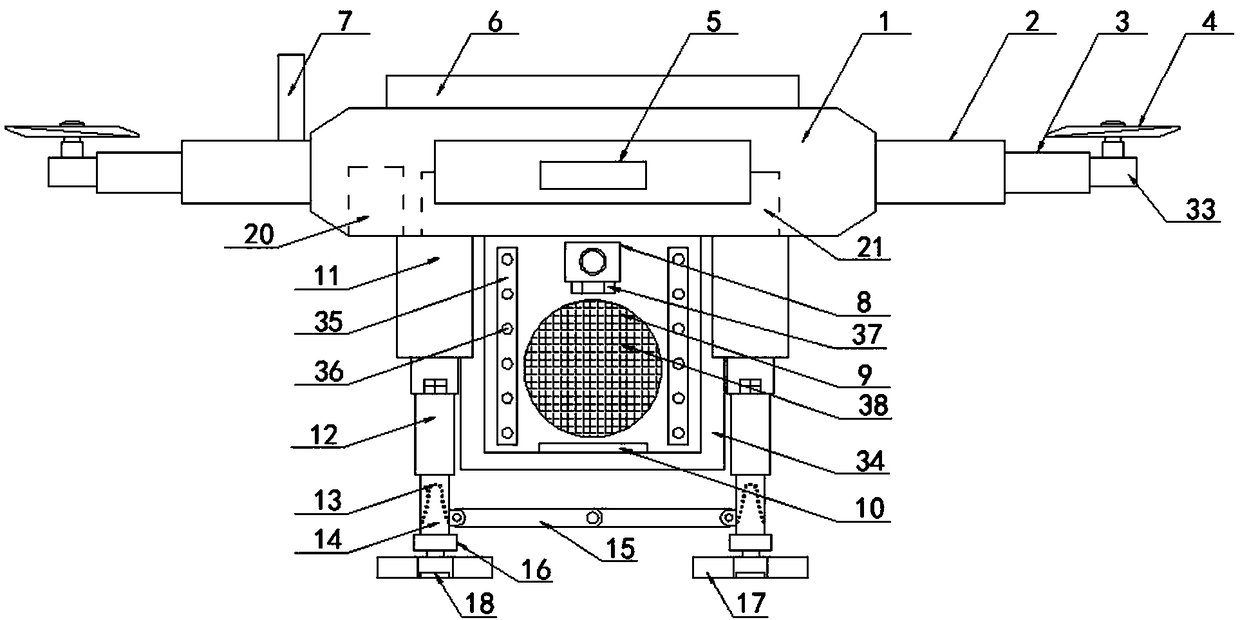
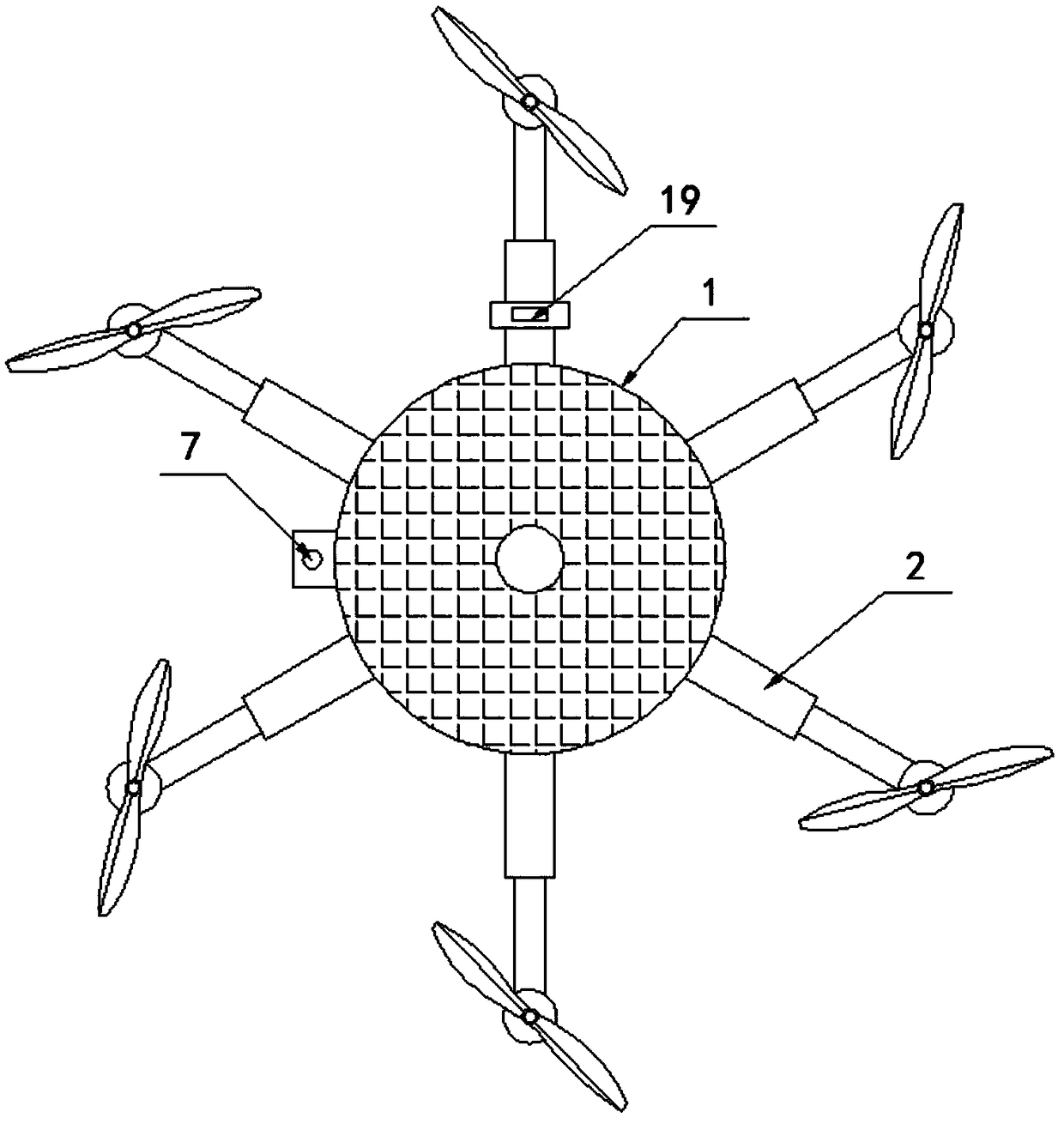
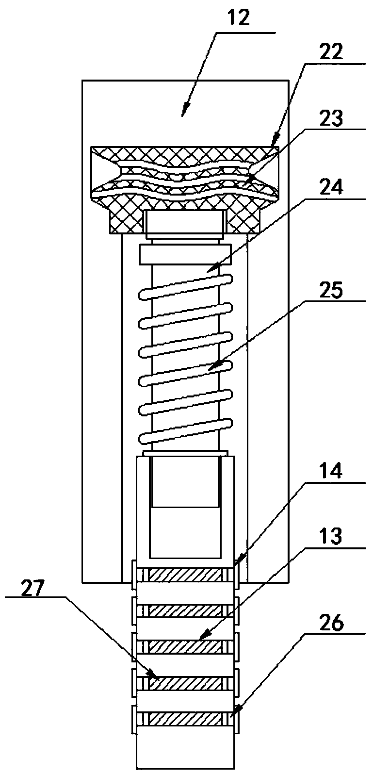
[0024] see Figure 1-5 , the present invention provides a technical solution: a traffic light type rotor UAV, including a body 1, a fixed block 34 is fixed on the bottom of the body 1, the fixed block 34 is a cube and signal lights 9 are arranged on all sides, and the surface of the signal lights 9 is uniformly arranged There are several smog compensating lamp beads 38, a high-definition camera 8 is fixed on the top of the signal light 9, a smog detector 37 is...


PUM


Abstract

The invention discloses a red and green light type rotary wing unmanned aerial vehicle. The red and green light type rotary wing unmanned aerial vehicle comprises a vehicle body, a fixed block is fixed at the bottom of the vehicle body, the fixed block is of a cube shape and signal lamps are arranged on the peripheral of the fixed block, and a plurality of haze compensation lamp beads are arrangedevenly on the surfaces of the signal lamps. High-definition cameras are fixed to the top of the signal lamps, haze detectors are fixed to the bottom of the high-definition cameras, and the surface ofthe fixed block is symmetrically connected with reflective strips in a bonded mode. Six first arms are arranged on the peripheral of the edge of the vehicle body at equal intervals, and GPS positioning devices are arranged on the first arms. Second arms are connected to the free ends of the first arms, and motors are connected to the tail ends of the second arms. Four electric push rods are fixedto the bottom of the vehicle body, the power output ends of the electric push rods are downward and connected with sleeve rods, and shock absorber rods are connected to the bottom of the sleeve rods.According to the red and green light type rotary wing unmanned aerial vehicle, the traffic light is arranged on the unmanned aerial vehicle, and traffic command can be carried out in time after the failure of the traffic signal light, so that long-term congestion of a road is avoided, and the use of the traffic light is less limited.

Description

technical field [0001] The invention relates to the technical field of unmanned aerial vehicles, and more specifically relates to a traffic light type rotor unmanned aerial vehicle. Background technique [0002] At the intersection, red, yellow, green and three-color traffic lights are hung on all sides. It is a silent "traffic policeman". Traffic lights are internationally unified traffic lights. A red light is a stop signal and a green light is a go signal. At the intersection, cars coming from several directions gather here, some will go straight, some will turn, and whoever is allowed to go first, here it is to obey the traffic light command. When the red light is on, it is forbidden to go straight or turn left, and vehicles are allowed to turn right under the condition of not hindering pedestrians and vehicles; when the green light is on, vehicles are allowed to go straight or turn; When the yellow light flashes, it warns the vehicle to pay attention to safety. In r...

Claims


Application Information

Patent Timeline
IPC IPC(8): B64C27/08B64D47/02B64C25/62B64C25/64G08G1/0955
CPCG08G1/0955B64C25/62B64C25/64B64C27/08B64D47/02B64U2101/00
Inventor 何诚舒立福张思玉刘柯珍王越
Owner NANJING FOREST POLICE COLLEGE
Learn More