Automatic feeding mechanism for yarn winding drums

An automatic feeding and reeling technology, applied in the automatic feeding mechanism of yarn reels, continuous feeding and winding of yarn reels, can solve the problem of long-term stable operation, prone to failure, difficult to meet large Problems such as batch yarn production, to achieve the effect of improving the degree of automation and reasonable structure design

Inactive Publication Date: 2019-02-01
桐乡市富利来针织股份有限公司
View PDF0 Cites 21 Cited by
  • Summary
  • Abstract
  • Description
  • Claims
  • Application Information

AI Technical Summary

Problems solved by technology

During the processing and winding process of the existing yarn, it is necessary to manually place the empty yarn reels one by one to the winding station to wind the yarn. The yarn reels are smoothly and accurately placed to the required position one by one, and for modern large-scale yarn production, manual operation is difficult to meet the needs of large-scale yarn production. The existing yarn reels are mainly loaded by manipulators. After the yarn reel is grabbed, it is moved and placed to the required winding station according to the needs. Since the yarn reel is an overall circular I-shaped structure, it is difficult for the manipulator to grab the yarn reel smoothly and accurately. In the process of grabbing the yarn reel, the yarn reel often falls off because the yarn reel is difficult to be grasped and fixed smoothly and firmly, and because it needs to be adjusted synchronously during the feeding process of the yarn reel The feeding station of the yarn reel requires multiple driving mechanisms to drive the manipulator continuously and independently. The driving energy consumption is high, and the multi-driving mechanisms are also prone to failure, making it difficult to run stably for a long period of time, reducing the yarn The efficiency and quality of the continuous transfer and feeding of the reels is difficult to realize the smooth transfer and feeding of the yarn reels one by one, and it is difficult to accurately and smoothly transfer the yarn reels to the desired position, and the automation of the yarn reel feeding The degree is low and cannot meet the needs of production and use

Method used


Image

  • Automatic feeding mechanism for yarn winding drums
  • Automatic feeding mechanism for yarn winding drums
  • Automatic feeding mechanism for yarn winding drums

Examples


Embodiment Construction

[0020] In order to further describe the present invention, a specific implementation of an automatic yarn reel feeding mechanism will be further described below in conjunction with the accompanying drawings. The following examples are explanations of the present invention and the present invention is not limited to the following examples.

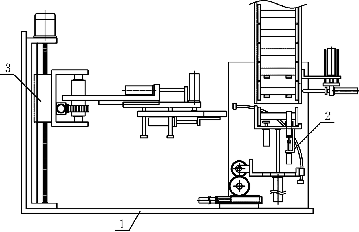
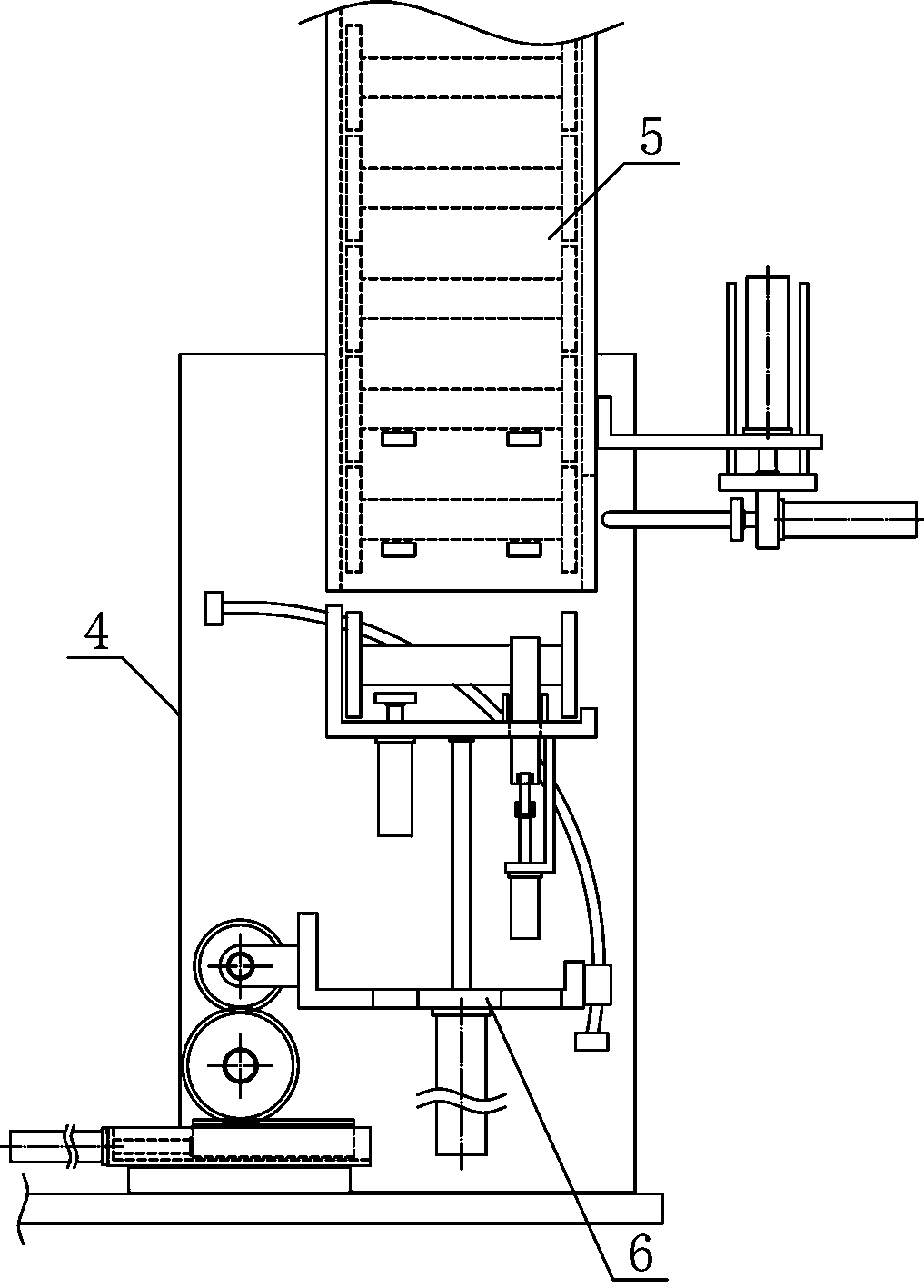
[0021] Such as figure 1 As shown, an automatic yarn reel feeding mechanism of the present invention includes a feeding base 1, a transfer mechanism 2 and a barrel transfer mechanism 3, and the transfer mechanism 2 and the barrel transfer mechanism 3 are vertically and vertically arranged on the feeding mechanism along the horizontal direction. Both sides above base 1, such as figure 2 As shown, the transfer mechanism 2 of the present invention includes a transfer bracket 4, a guide cylinder mechanism 5 and a rotating cylinder mechanism 6, and the guide cylinder mechanism 5 and the rotating cylinder mechanism 6 are vertically and fixedly ar...


PUM


Abstract

The invention discloses an automatic feeding mechanism for yarn winding drums, and belongs to the field of fabric production and processing machinery and equipment. A transfer mechanism and barrel moving mechanism of the automatic feeding mechanism are sequentially, vertically and fixedly arranged on the two sides of the upper portion of a feeding base in the horizontal direction. A barrel guidingmechanism and a barrel turning mechanism are sequentially, vertically and fixedly arranged on one side of a transfer bracket from top to bottom. A barrel guiding material pipe is vertically and fixedly arranged on one side of the transfer bracket. A barrel placing bracket is horizontally and fixedly arranged at the output end of a barrel bearing cylinder in the middle of the lower side of a reciprocating bracket. A rotating bracket is horizontally and fixedly arranged on the middle portion of a rotating sleeve of a barrel moving bracket. A barrel moving connecting plate is horizontally arranged at the lower side of a translation connecting plate, and a barrel bearing clamping plate is horizontally and fixedly arranged at the output end of a clamping plate cylinder. The automatic feeding mechanism is reasonable in structural design, can smoothly transfer and feed the yarn winding drums one by one and smoothly transfer and place the yarn winding drums to required positions, improves theautomation degree of feeding the yarn winding drums, and meets the requirements of production and use.

Description

technical field [0001] The invention belongs to the field of fabric production and processing machinery, and in particular relates to an automatic feeding mechanism for yarn reels, which is mainly used for continuous feeding and winding of yarn reels. Background technique [0002] Yarn is the basic raw material for fabric weaving. Knitted fabrics can be classified into weft-knitted fabrics and warp-knitted fabrics according to the weaving method. Commonly used weft-knitted fabrics are mainly made of low-elastic polyester yarn or special-shaped polyester yarn, nylon yarn , cotton yarn, wool yarn, etc. are used as raw materials, and are woven on various weft knitting machines using plain stitches, variable flat stitches, rib plain stitches, double rib plain stitches, jacquard stitches, and terry stitches. Yarn is the basic raw material for fabric weaving. In the process of yarn production and processing, it is necessary to wind the incoming cotton yarn into a yarn reel with a ...

Claims


Application Information

Patent Timeline
Patent Type & Authority Applications(China)
IPC IPC(8): B65H67/06
CPCB65H67/068
Inventor 吴晨键
Owner 桐乡市富利来针织股份有限公司
Why Eureka
Try Eureka