Treating device for sewage in sludge

A technology of treatment device and sewage, applied in water/sludge/sewage treatment, sludge treatment, water/sewage treatment, etc., can solve the problems of insufficient filtration, waste of water resources, increased workload of sewage treatment units, etc. The purification effect is remarkable and the effect of improving the purification efficiency

Inactive Publication Date: 2019-02-01
贺昭华
View PDF0 Cites 7 Cited by
  • Summary
  • Abstract
  • Description
  • Claims
  • Application Information

AI Technical Summary

Problems solved by technology

[0002] At present, China's water resources are extremely scarce, and people's awareness of water conservation still needs to be improved. It is difficult to achieve the goal by people's own water conservation, and it is not feasible to restrict people's economic level by raising water prices. It is necessary to improve domestic water waste
At present, the discharge of wastewater shows a rapid growth trend, which not only causes a great waste of water resources, but also increases the workload of sewage treatment units. Among them, the previous sludge treatment and filtration is not thorough enough, resulting in poor sewage filtration effect

Method used


Image

  • Treating device for sewage in sludge
  • Treating device for sewage in sludge
  • Treating device for sewage in sludge

Examples


Embodiment 1

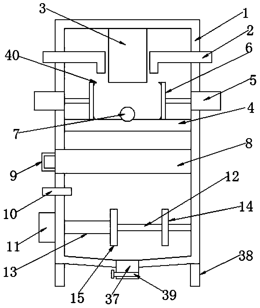
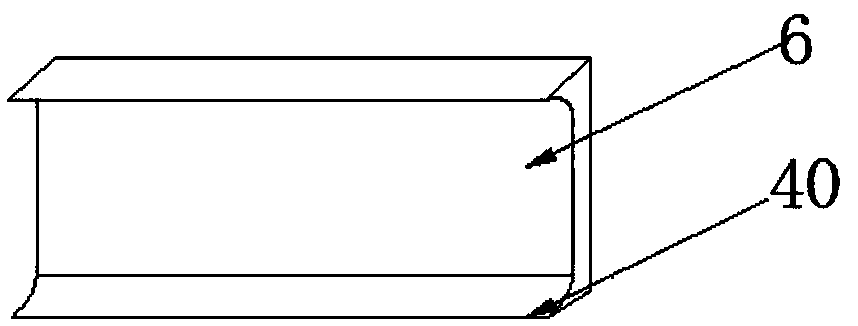
[0028] Embodiment one, such as Figure 1-4 As shown, a treatment device for sewage in sludge according to an embodiment of the present invention includes a housing 1, and both sides of the upper end of the housing 1 are provided with sewage inlet pipes 2, and the inner wall of the housing 1 And between the two groups of sewage inlet pipes 2, an extruding device 3 is arranged, and a filter plate 4 is fixedly installed under the extruding device 3 and in the middle of the interior of the housing 1, and the filter plate 4 Both sides of the upper end and both sides of the housing 1 are provided with a telescopic cylinder 5, the output end of the telescopic cylinder 5 is connected to one side of the scraper 6, and one side of the filter plate 4 is located in the two groups. A sewage outlet 7 is arranged between the scrapers 6, and a sewage purifier 8 is provided at the lower end of the filter plate 4 and inside the housing 1, and one side of the sewage purifier 8 is located at the ...

Embodiment 2

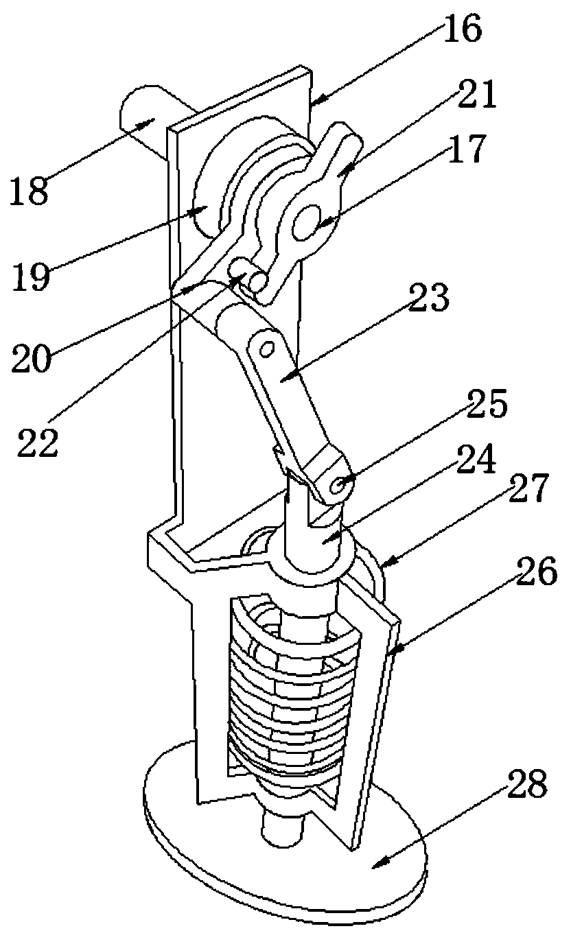
[0029] Embodiment two, such as Figure 1-3 As shown, the extrusion device 3 includes a fixed plate 16, and the fixed plate 16 is fixedly connected to the inside of the housing 1, the upper end of the fixed plate 16 is interspersed with a rotating shaft 17, and the rotating shaft 1 One end of 17 is provided with a motor 18 on one side of the fixed plate 16, and the other end of the rotating shaft 17 is provided with a connecting block 19, a movable block 20 and a limiter on the other side of the fixed plate 16 in turn. Block 21, one side of the movable block 20 is provided with a limit post 22 matched with the limit block 21, the lower end of the movable block 20 is connected with one end of the connecting rod 23 through a shaft, and the connecting rod The other end of 23 is connected with the upper end of movable rod 24 by rotating shaft two 25, and the lower end side of described fixed plate 16 is provided with fixed mount 26, and described movable rod 24 runs through the inb...

Embodiment 3

[0030] Embodiment three, such as figure 1 and Figure 4As shown, the inside of the gear box 11 is provided with a gear ring 30, and the inner side of the gear ring 30 is provided with a gear one 31 and a gear two 32 matched with the gear ring 30, and the movable shaft 12 One end is inserted in the center position of the first gear 31, the center position of the second gear 32 is interspersed with a rotating shaft three 33, and one side of the first gear 31 is sleeved with a gear three 34 on the movable shaft 12, One side of the second gear 31 and on the third shaft 33 is provided with a fourth gear 35 matched with the third gear 34, and the ring gear 30 is mutually connected with the first gear 31 and the second gear 32. Engagement, the gear three 34 and the gear four 35 mesh with each other, and one side of the gear three 34 and the gear four 35 is provided with a fixed block 36, it is characterized in that the gear three 34 passes through the The sleeve 13 is connected to ...


PUM


Abstract

The invention discloses a treating device for sewage in sludge. The treating device comprises a shell, sewage inlet pipes are penetratingly arranged on two sides of an inner upper end of the shell, asqueezing device is arranged on an inner wall of the shell and is positioned between the two sewage inlet pipes, a filtering plate is fixedly mounted below the squeezing device and is positioned in the inner middle of shell, telescopic cylinders are respectively arranged on two sides of an upper end of the filtering plate and are also positioned on two sides of the shell, output ends of the telescopic cylinders are connected with one sides of scrapping plates, a drain outlet is formed in one side of the filtering plate and is positioned between the two scrapping plates, a sewage purifier is arranged at a lower end of the filtering plate and is positioned inside the shell, a handle is arranged on one side, outside the shell, of the sewage purifier, a feeding pipe is arranged at a lower endof the handle and is positioned outside the shell, a gearbox is arranged at the lower end of the feeding pipe and is positioned outside the shell, a movable shaft is arranged on one side of the gearbox and is positioned inside the shell, a sleeve is arranged on one side of the movable shaft in a sleeved manner, a second stirring rod is arranged at one end of the movable shaft, and a second stirring rod is arranged at one end of the sleeve.

Description

technical field [0001] The invention relates to the field of sewage treatment, in particular to a treatment device for sewage in sludge. Background technique [0002] At present, China's water resources are extremely scarce, and people's awareness of water conservation still needs to be improved. It is difficult to achieve the goal by people's own water conservation, and it is not feasible to restrict people's economic level by raising water prices. It is necessary to improve domestic water waste. At present, the discharge of wastewater shows a rapid growth trend, which not only causes a great waste of water resources, but also increases the workload of sewage treatment units. Among them, the previous sludge treatment and filtration is not thorough enough, resulting in poor sewage filtration effect. Contents of the invention [0003] The technical task of the present invention is to provide a treatment device for sewage in sludge to solve the problem of improving sewage t...

Claims


Application Information

Patent Timeline
Patent Type & Authority Applications(China)
IPC IPC(8): C02F11/121C02F1/00B01F7/04
CPCC02F1/00C02F11/122B01F27/70B01F2101/305
Inventor 贺昭华
Owner 贺昭华
Why Eureka
Try Eureka