Electrochemical in-situ decontamination of radioactive contaminants on metal surfaces

A metal surface and electrochemical technology, applied in the direction of electrolytic components, electrolytic process, etc., can solve the problems of inconvenient maintenance and use, high decontamination cost and complexity, etc., and achieve convenient use and maintenance, high decontamination precision and decontamination effect Good results

Active Publication Date: 2020-05-26
NUCLEAR POWER INSTITUTE OF CHINA
View PDF6 Cites 0 Cited by
  • Summary
  • Abstract
  • Description
  • Claims
  • Application Information

AI Technical Summary

Problems solved by technology

[0005] The purpose of the present invention is to provide an electrochemical in-situ decontamination method for radioactive pollutants on metal surfaces, so as to solve the complex decontamination process for difficult and non-detachable metal workpieces in the prior art, and the decontamination cost caused by untargeted radionuclides High, and the complex structure of the electrochemical decontamination device is not easy to maintain and use

Method used


Image

  • Electrochemical in-situ decontamination of radioactive contaminants on metal surfaces
  • Electrochemical in-situ decontamination of radioactive contaminants on metal surfaces
  • Electrochemical in-situ decontamination of radioactive contaminants on metal surfaces

Examples


Embodiment 1

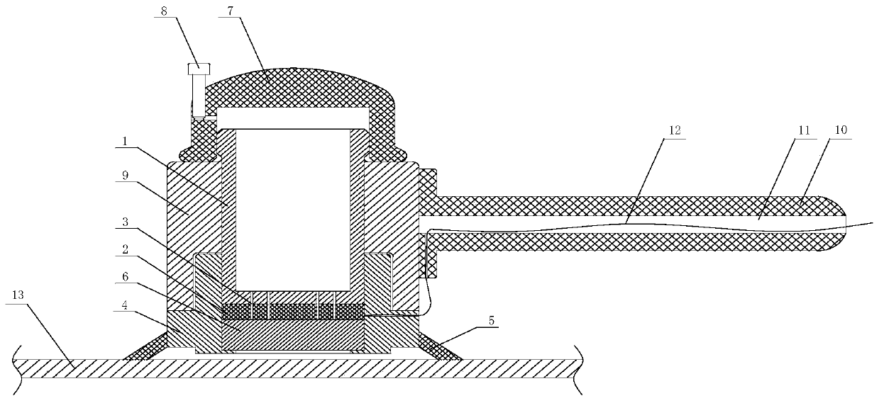
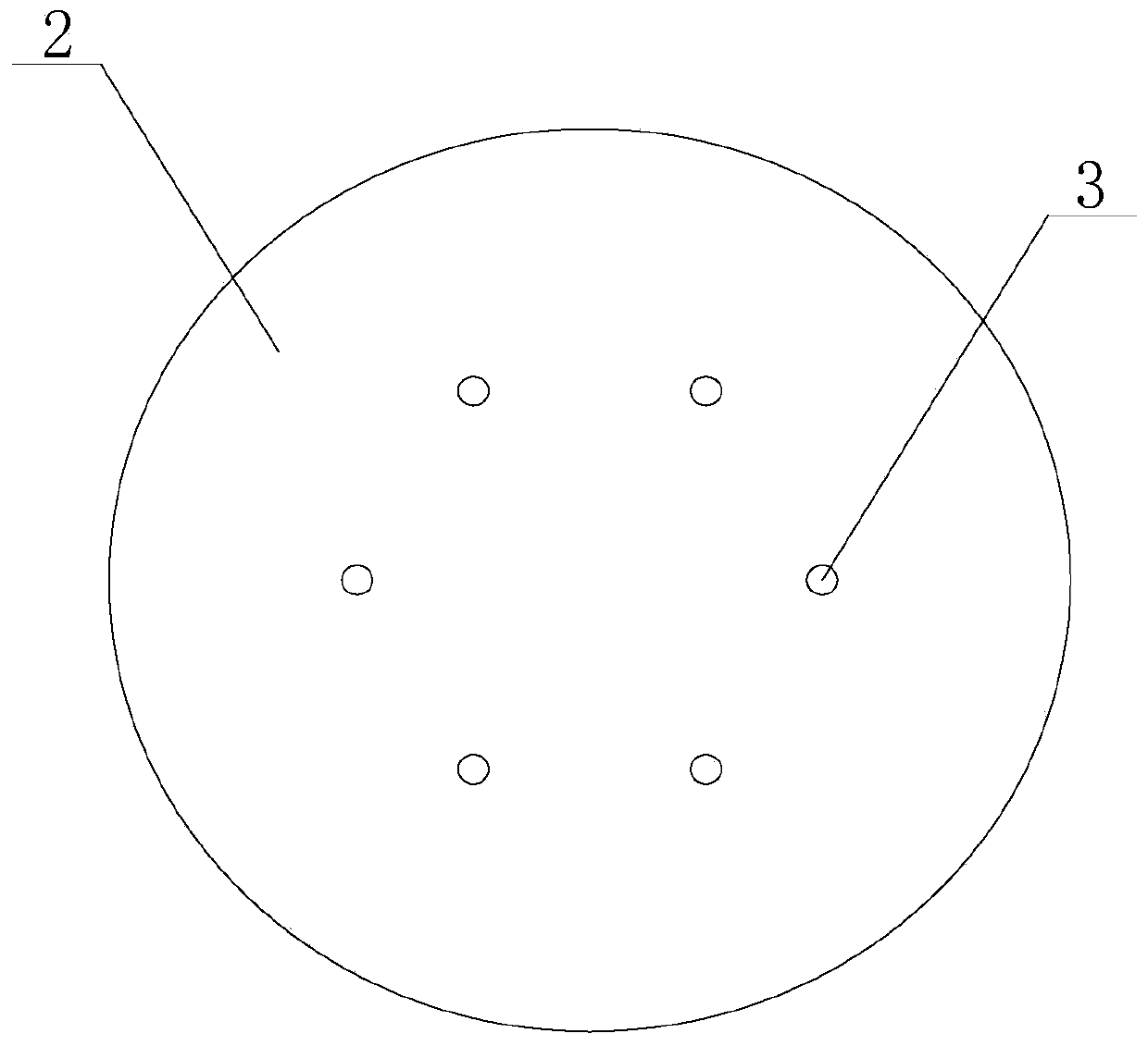
[0056] Such as Figure 1 to Figure 3 The embodiment shown, the electrochemical in-situ decontamination method of radioactive pollutants on the metal surface, the method uses an electrochemical decontamination system, and the electrochemical decontamination system includes a DC stabilized voltage power supply, an anode metal clip and a portable electrochemical cathode device, The portable electrochemical cathode device includes a liquid storage tank 1, a cathode plate 2 is installed below the liquid storage tank 1, a lead 12 is connected to the cathode plate 2, a through hole 3 is arranged at the bottom of the liquid storage tank 1, and the bottom of the through hole 3 is sequentially Through the liquid storage tank 1 and the cathode plate 2; the outside of the liquid storage tank 1 is detachably connected to an anode contactor 4, and the anode contactor 4 is provided with a housing chamber for accommodating the cathode plate 2, and the housing chamber is also A filling pad 6 l...

Embodiment 2

[0066] On the basis of Embodiment 1, the portable electrochemical cathode device also includes a top cover 7 positioned above the liquid storage tank 1, the top cover 7 is provided with an adjustment through hole, and the adjustment through hole communicates with the inner space and the outer space of the top cover 7, The top cover 7 is provided with an adjusting bolt 8 and an adjusting screw hole matching the adjusting bolt 8, and the adjusting screw hole communicates with the adjusting through hole; the bottom of the adjusting bolt 8 is provided with a gasket; the outer side of the liquid storage tank 1 A housing 9 located above the anode contactor 4 is sheathed, and a handle 10 is connected to the housing 9 , and a wiring groove 11 is arranged in the handle 10 .

[0067] Through the top cover 7, the adjustment through hole, the adjustment bolt 8, and the adjustment screw hole, the user can adjust the penetration speed of the electrolyte according to actual needs during opera...


PUM

PropertyMeasurementUnit
clearance rateaaaaaaaaaa

Abstract

The invention discloses an electrochemical in-situ decontamination method for radioactive pollutants on metal surfaces. The bottom end runs through the liquid storage tank and the cathode plate in turn; an anode contactor is detachably connected to the outside of the liquid storage tank. The interior and the bottom surface of the anode contactor form a cleaning chamber, and an opening is opened on the bottom of the anode contactor, and the opening communicates with the accommodating chamber and the cleaning chamber. For smaller polluted areas, the present invention can decontaminate the radionuclide area at a fixed point and in situ through the cleaning chamber formed by the anode contactor and the annular seal. The decontamination accuracy is high, the decontamination effect is good, and the electrolyte solution It is wasted on metal surfaces that do not need to be cleaned, which not only saves cleaning costs but also reduces the amount of secondary waste liquid.

Description

technical field [0001] The invention relates to the field of decommissioning of nuclear facilities and treatment of three wastes, in particular to an electrochemical in-situ decontamination method for radioactive pollutants on metal surfaces. Background technique [0002] In nuclear power plants, military nuclear power and research institutes, along with the operation, maintenance, inspection and regular overhaul of nuclear facility equipment, spent fuel reprocessing and decommissioning of nuclear facilities will produce a large number of detachable and difficult-to-detach metal contaminated parts. Such as pipes, glove boxes, etc. The main radionuclides deposited on the surface and attached to the pollution are 60 Co. 55 Fe, 63 Ni and 54 Mn. For the decontamination of nuclear facilities such as these metal contaminated parts, physical or chemical methods and means are mainly used to remove all or part of the contaminated radionuclides from the surface or inside, so as t...

Claims


Application Information

Patent Timeline
Patent Type & Authority Patents(China)
IPC IPC(8): C25F1/04C25F7/00
CPCC25F1/04C25F7/00
Inventor 鲁芸芸陈云明李兵曹骐张劲松陈旭敏严文超周蓉赵萍
Owner NUCLEAR POWER INSTITUTE OF CHINA
Why Eureka
Try Eureka