Bottom grout injection system and method suitable for deep well grounding electrode feed bar

A grouting system and grounding electrode technology, applied in the direction of connection contact material, infrastructure engineering, construction, etc., can solve the problems of small hole diameter of deep well grounding electrode, many equipment, and inability to use direct landfill, etc., and the grouting time can be achieved. control, grouting amount controllable effect

Pending Publication Date: 2019-02-01
GUANGDONG KENUO SURVEYING ENG CO LTD +2
View PDF7 Cites 3 Cited by
  • Summary
  • Abstract
  • Description
  • Claims
  • Application Information

AI Technical Summary

Problems solved by technology
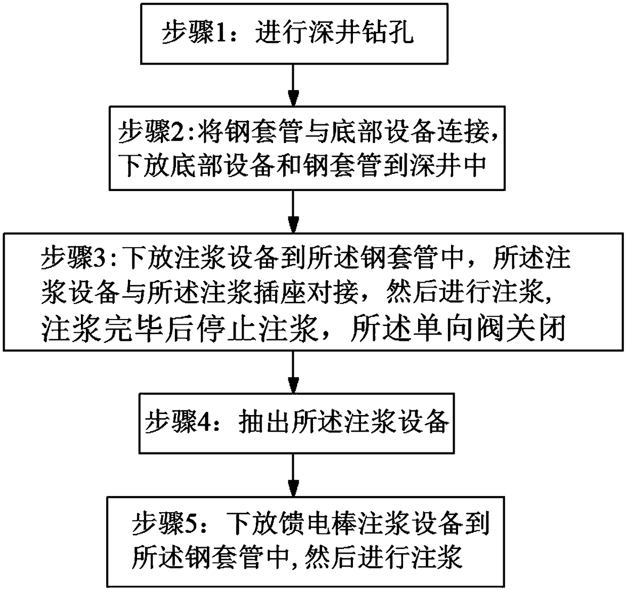
[0003] Coke particles are an important part of grounding electrodes. In the construction of conventional horizontal and vertical grounding electrodes, direct landfilling is often used. However, deep well grounding electrodes have small apertures, large buried depths, and many equipments, so direct landfilling cannot be adopted. Therefore, it is considered to use the method of grouting at the bottom of the hole for filling. The grouting at the bottom of the hole is widely used in oil, natural gas, geothermal and other exploration and production processes, but it is mostly used in the cementing process. big difference
[0004] The existing bottom grouting equipment does not consider the construction procedure and electrical equipment installation requirements of the deep well ground electrode. There is a big difference between the cementing and one-way grouting process and the deep well ground electrode coke filling process. It is necessary to consider the existing feeder in the deep well. In the case of electric rods, it is of great significance to design a grouting equipment that can fill the coke slurry completely and quickly in the diffuse flow section after bottom grouting. It is of great significance to break through engineering problems for the installation of deep well ground electrodes.

Method used


Image

  • Bottom grout injection system and method suitable for deep well grounding electrode feed bar
  • Bottom grout injection system and method suitable for deep well grounding electrode feed bar

Examples


Embodiment Construction

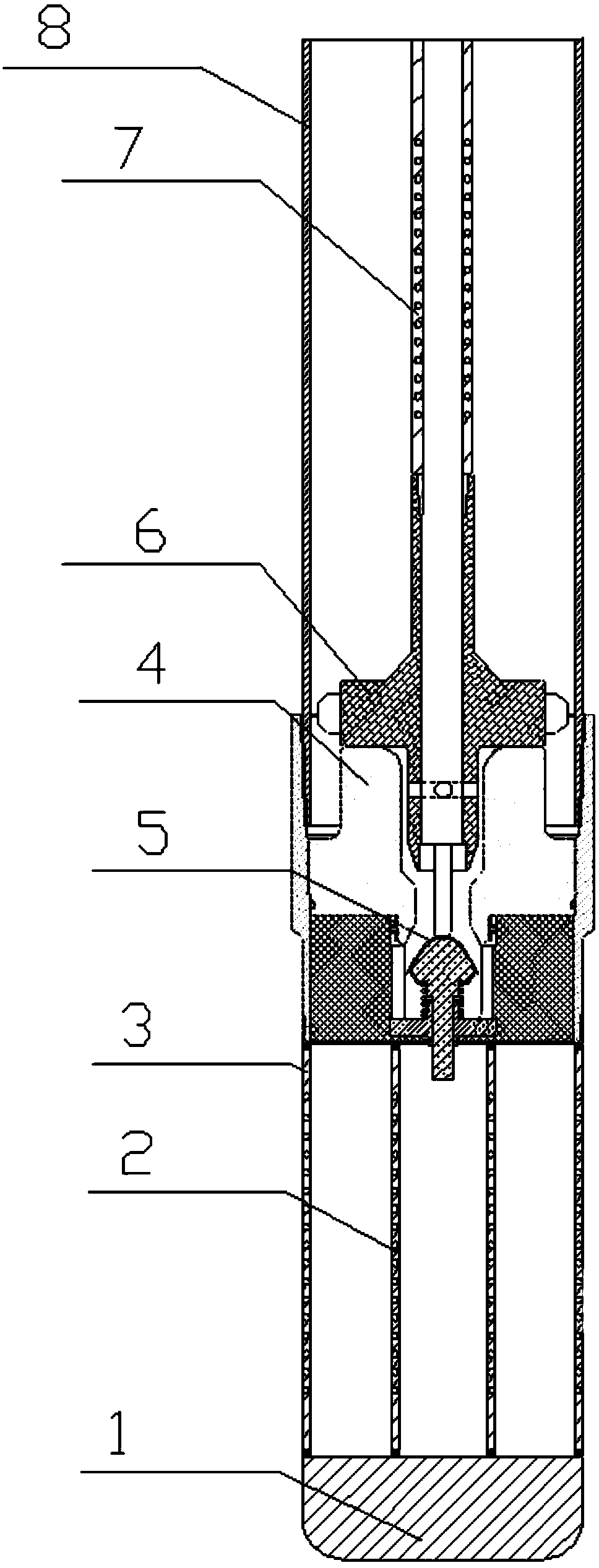
[0037] The invention provides a grouting system suitable for deep well grounding electrode feed rods, which can completely and quickly fill the coke slurry in the diffuse flow section after bottom grouting.

[0038] Please refer to the attached figure 1 , figure 1 It shows an embodiment of the bottom grouting system applicable to deep well ground electrode feeder rods of the present invention. This invention may, however, be embodied in many different forms and should not be construed as limited to the specific embodiments set forth herein.

[0039] Unless otherwise defined, terms (including technical and scientific terms) used herein should be understood to have the same meaning as commonly understood by those skilled in the art to which this invention belongs. Moreover, it is to be understood that the terms used herein should be understood to have a meaning consistent with the meaning in this specification and the relevant art, and should not be interpreted in an ideal or ...


PUM


Abstract

The invention relates to a bottom grout injection system suitable for a deep well grounding electrode feed bar. The grout injection system comprises a bottom steel column, an inner layer floral tube,an outer layer floral tube, a grout injection inserting base, a one-way valve, a centralizer containing plug, a grout injection pipe and a steel casing pipe; when the grout injection system starts grout injection, through the pressure of the centralizer containing plug, the one-way valve is started, water on the outer pipe of the steel casing pipe is supplemented into the steel casing pipe in time, and the phenomenon that when the feed bar is drained to the ground, due to temperature rise, water is evaporated, and a feed system fails is avoided.

Description

technical field [0001] The invention relates to the technical field of DC transmission engineering grounding, in particular to a bottom grouting system and a grouting method suitable for deep well grounding electrode feed rods. Background technique [0002] As an important part of the DC transmission project, the DC grounding electrode is now commonly used in two types of land grounding electrode technology: horizontal grounding electrode and vertical grounding electrode. The existing grounding electrodes have disadvantages such as large floor area, difficult site selection, and great impact on the shallow environment around the electrode site. The deep well grounding electrode technology can effectively avoid the above-mentioned problems. After the deep well drilling is completed, in order to install the follow-up equipment smoothly, it is necessary to lower the protective wall steel casing first, and then lower the drainage and feeder rods. In order to increase the connect...

Claims


Application Information

Patent Timeline
Patent Type & Authority Applications(China)
IPC IPC(8): E02D15/00H01R4/66
CPCH01R4/66E02D15/00
Inventor 王小明程小久汪华安刘东生李海云孙合平颜斌冉启华洪艳楼许兵罗鸣
Owner GUANGDONG KENUO SURVEYING ENG CO LTD
Why Eureka
Try Eureka