Eureka AIR delivers breakthrough ideas for toughest innovation challenges, trusted by R&D personnel around the world.

Novel assembly type planting roof drainage groove and drainage system

A drainage system and prefabricated technology, applied in the direction of roof drainage, roof, roof covering, etc., can solve the problems of increasing the difficulty of on-site splicing by construction personnel, increasing the difficulty and complexity of construction, and increasing the difficulty of planting roof construction, etc., to achieve Strong designability, reduce the difficulty and complexity of assembly, and avoid the effect of roof moisture seepage

Pending Publication Date: 2019-02-01
KESHUN WATERPROOF TECH CO LTD
View PDF0 Cites 3 Cited by
  • Summary
  • Abstract
  • Description
  • Claims
  • Application Information

AI Technical Summary

Problems solved by technology

Although this scheme can form a network by plugging multiple drainage tank bodies with different structures, each drainage tank body in this scheme is provided with a drainage port, which makes it difficult to achieve the same discharge effect on the rainwater collected by the planted roof
Since the drainage outlet needs to be connected with external drainage pipes, it is easy to cause the drainage pipes to be too dense, which increases the difficulty and complexity of construction
In addition, the drainage tank bodies of all structures in the scheme are equipped with ventilation observation ports. If the length of the drainage tank body is not long enough, even if only one ventilation observation port is provided for each drainage tank, it is easy to cause the ventilation observation ports to be set too densely. It also increases the construction difficulty of planting the roof; and if the length of the gutter body is set long enough, the storage, transportation and handling of the gutter body will be a big problem. Difficulty of on-site splicing

Method used


Image

  • Novel assembly type planting roof drainage groove and drainage system
  • Novel assembly type planting roof drainage groove and drainage system
  • Novel assembly type planting roof drainage groove and drainage system

Examples


Embodiment

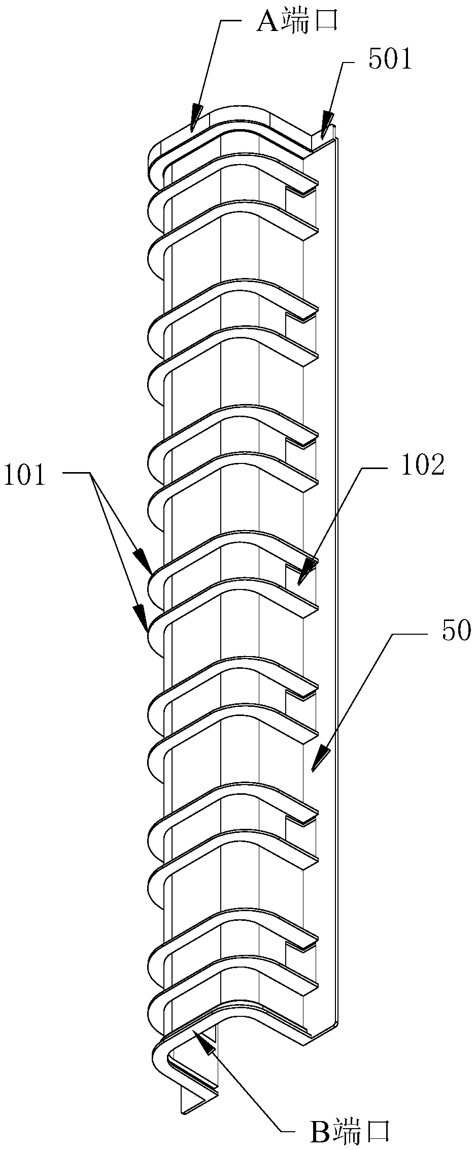
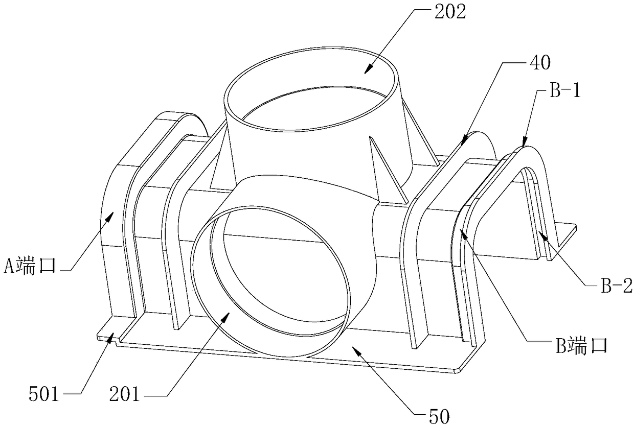
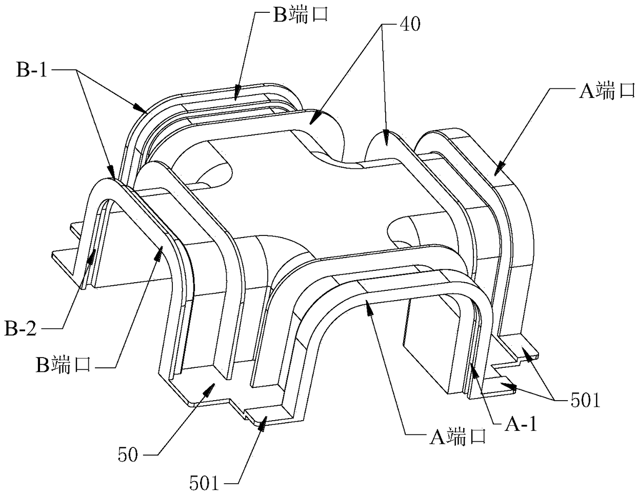
[0038] This embodiment provides a new type of assembled planting roof gutter, such as Figure 1~3 As shown, it includes drainage blind groove 1, three-way drainage assembly 2 and four-way drainage assembly 3. The drainage blind groove 1, the three-way drainage assembly 2 and the four-way drainage assembly 3 are all provided with an A port and a B port which can engage with each other to realize assembly connection.

[0039] Wherein, the A port is provided with a first groove A-1, and the B port is provided with an upwardly protruding rib structure B-1. During assembly, by pressing down the first groove of the A port against the B port, the protruding strip structure of the B port is inserted into the first groove of the A port, so as to realize the assembly connection. This assembly method is to achieve a fixed connection by snapping up and down between the A port and the B port.

[0040] Such as figure 1 As shown, the drainage blind groove 1 is a groove body with an invert...


PUM


Abstract

The invention discloses a novel assembly type planting roof drainage groove. The novel assembly type planting roof drainage groove comprises a drainage blind groove, a three-way drainage assembly anda four-way drainage assembly. The drainage blind groove is a groove body with two ends opened. A protruding strip is arranged at one end of the drainage blind groove. A groove used for the protrudingstrip to insert in formed in the other end of the drainage blind groove. Water storing holes are formed in the lateral face of the drainage blind groove. The three-way drainage assembly comprises three openings. A protruding strip is arranged at one opening. A groove used for the protruding strip to insert is formed in one opening. A drainage opening is formed in another opening. The four-way drainage assembly comprises four openings. A protruding strip is arranged at one opening. A groove used for the protruding strip to insert is formed in one opening. A protruding strip / groove used for theprotruding strip to insert is formed in the rest two openings. The openings provided with the grooves can be matched with the openings provided with the protruding strips in an up and down mode to achieve sealing connection. Ventilation pipe inserting openings are formed in the upper portion of the three-way drainage assembly and / or the four-way drainage assembly. The structure is simple, assembling is flexible and convenient, mounting difficulty is little, and mounting space requirements are few.

Description

technical field [0001] The invention relates to the field of planting roof drainage, in particular to a novel assembled planting roof drainage groove and drainage system. Background technique [0002] Planting roof is a form of greening that supplements planting soil, planting plants in containers or planting templates to cover building roofs or underground building roofs. [0003] At present, drainage boards are mostly used for the drainage of planted roofs. However, the existing drainage board is to form a solid or cup-shaped protrusion on the polymer sheet. The mouth of the cup-shaped protrusion is in the opposite direction of the protrusion, and the protrusion is generally upward, and the space between the protrusions forms a drainage channel. . When the protrusions are down, holes are punched between the protrusions, and water passes through the holes and flows away from the spaces between the protrusions. The drainage system using drainage boards in the prior art is...

Claims


Application Information

Patent Timeline
Patent Type & Authority Applications(China)
IPC IPC(8): E04D13/04
CPCE04D13/0445
Inventor 周波叶吉宋桃
Owner KESHUN WATERPROOF TECH CO LTD
Why Eureka
Eureka Blog
Learn More