
Heat regenerator, miniature gas turbine and miniature gas turbine generator unit

A micro gas turbine and regenerator technology, which is applied to gas turbine devices, machines/engines, mechanical equipment, etc., can solve the problems of limited heat exchange area of ​​heat exchangers, limited engine installation positions, and difficulty in improving heat exchange efficiency. Achieve high yield, solve mass production problems, and be easy to process.

Pending Publication Date: 2019-02-01
刘慕华
View PDF0 Cites 5 Cited by
  • Summary
  • Abstract
  • Description
  • Claims
  • Application Information

AI Technical Summary

Problems solved by technology

[0003] However, there are multiple problems in the regenerator in the prior art, specifically as follows: (1), the heat exchange area is the surface area of ​​the heat exchange tube, and due to the limited surface area of ​​the heat exchange tube, the heat exchange area of ​​the heat exchanger is limited, As a result, it is difficult to improve the heat exchange efficiency; (2), the shape of the shell is usually a cylindrical structure, and its volume is large, resulting in a large installation space required and limited use; (3), the cylindrical structure When the heat exchanger is applied to the engine, it is usually sleeved outside the combustion chamber, which increases the volume of the engine and limits the installation position of the engine

Method used


Image

  • Heat regenerator, miniature gas turbine and miniature gas turbine generator unit
  • Heat regenerator, miniature gas turbine and miniature gas turbine generator unit
  • Heat regenerator, miniature gas turbine and miniature gas turbine generator unit

Examples


Embodiment Construction

[0058] In describing the present invention, it should be understood that the terms "center", "longitudinal", "transverse", "length", "width", "thickness", "upper", "lower", "front", " Back", "Left", "Right", "Vertical", "Horizontal", "Top", "Bottom", "Inner", "Outer", "Clockwise", "Counterclockwise", "Axial", The orientation or positional relationship indicated by "radial", "circumferential", etc. is based on the orientation or positional relationship shown in the drawings, and is only for the convenience of describing the present invention and simplifying the description, rather than indicating or implying the referred device or element Must be in a particular orientation, be constructed in a particular orientation, and operate in a particular orientation, and therefore should not be construed as limiting the invention. In addition, the features defined as "first" and "second" may explicitly or implicitly include one or more of these features. In the description of the prese...


PUM

PropertyMeasurementUnit
Heightaaaaaaaaaa
Heightaaaaaaaaaa

Abstract

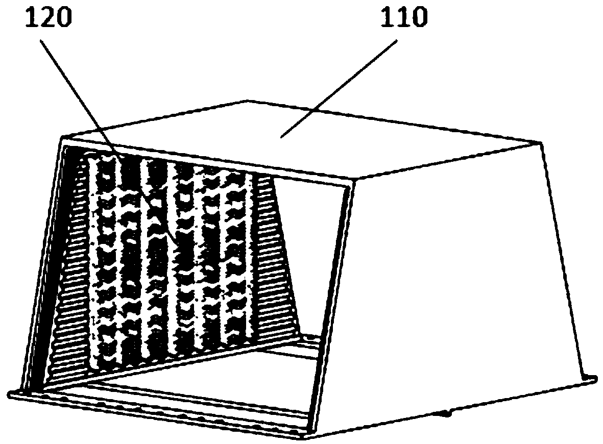
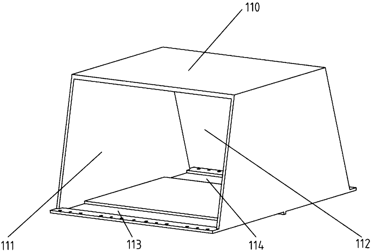
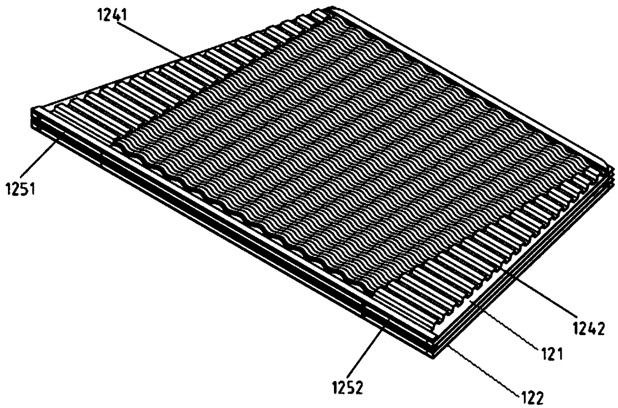
Disclosed are a heat regenerator, a miniature gas turbine comprising the heat regenerator and a miniature gas turbine generator unit. The heat regenerator comprises a shell and a plurality of heat exchanging plates; each heat exchanging plate comprises a first heat exchanging element, a second medium flow-guiding sheet and a second heat exchanging element, and the first heat exchanging elements and the second heat exchanging elements each comprise a first medium flow-guiding sheet I, a heat exchanging fin and a first medium flow-guiding sheet II; first medium channels are formed by the heat exchanging fins of the first heat exchanging elements and the second heat exchanging elements of the adjacent heat exchanging plates; and a second medium channel is formed by the heat exchanging fins ofthe first heat exchanging element and the second heat exchanging element of each heat exchanging plate. According to the heat regenerator, the heat exchanging efficiency is improved by increasing theheat exchanging area, and the size is decreased so that the heat regenerator can be applied modularly, and compressed gas introduced into a combustor is heated through heat of high-temperature tail gas so as to increase the combustion rate of fuel.

Description

technical field [0001] The invention relates to the technical field of heat exchange equipment, in particular to a regenerator, a micro gas turbine installed with the regenerator and a micro gas turbine generating set. Background technique [0002] Regenerator, also known as heat exchanger, is a device that exchanges heat between two fluids flowing through it. In the heat exchangers of the prior art, a plurality of heat exchange tubes are usually arranged in a shell, or heat exchange tubes in the form of coils are arranged in the shell, so as to increase the heat exchange area and improve the heat exchange efficiency. For micro gas turbines, installing a regenerator to increase the temperature of the gas turbine's charge air can greatly improve its energy conversion efficiency. The regenerator mainly uses the high-temperature exhaust gas discharged from the micro gas turbine to heat the pressurized air from the compressor, and then enters the combustion chamber for combusti...

Claims


Application Information

Patent Timeline
IPC IPC(8): F02C7/08F02C7/00F02C6/00
CPCF02C6/00F02C7/00F02C7/08
Inventor 靳普尹红蛟陈玉渊王经纬
Owner 刘慕华
Learn More