

Swing power generation device
A power generation device and swing connection technology, which is applied in the field of swing power generation devices, can solve the problems of insufficient use of ocean buoyancy, affect power generation efficiency, and general swing effect, and achieve the effects of improving energy utilization efficiency, ingenious structural design, and improving swing effect.
- Summary
- Abstract
- Description
- Claims
- Application Information
AI Technical Summary
Problems solved by technology
Method used
Image

Examples
Embodiment 1
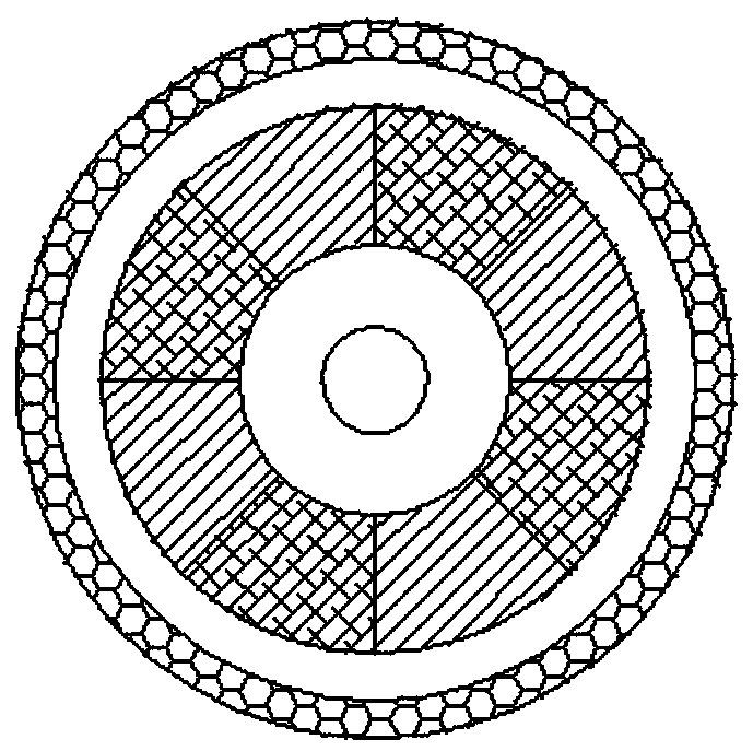
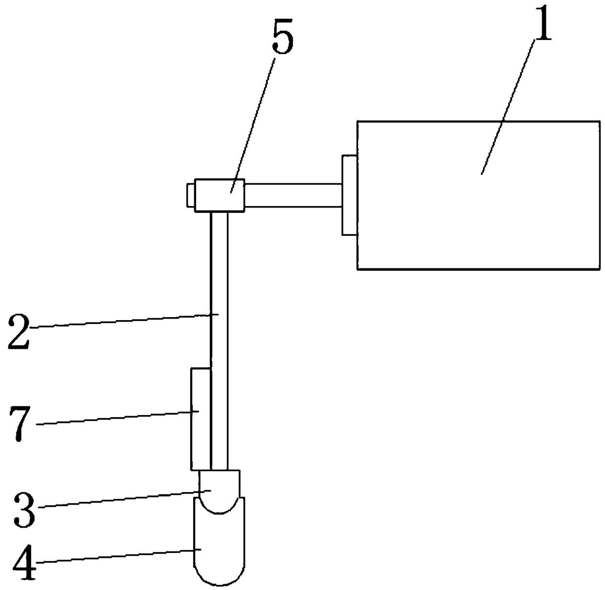
[0029] see Figure 1 to Figure 4 As shown, this embodiment provides a swing power generation device, which converts the wave energy of seawater into electric energy, including a generator 1, a swing connector 2, a pendulum 3, a floating package 4, a one-way bearing 5, a fixed groove 6 and auxiliary device7.
[0030] The main structure of generator 1 is as follows: figure 1 As shown, it includes a rotor and a stator. The rotor is provided with magnets around the circumference to form a fixed magnetic field for coil cutting. The outside of the rotor is a stator wound with coils. Through the relative rotation of the rotor in the stator, the coil cuts the magnetic field. Generate electrical energy and store the electrical energy on the electrical storage device through the wire. In order to generate electricity by utilizing the wave energy of seawater, specifically, a one-way bearing 5 is provided on the output shaft of the rotor of the generator 1, so that the rotor can only ro...
Embodiment 2
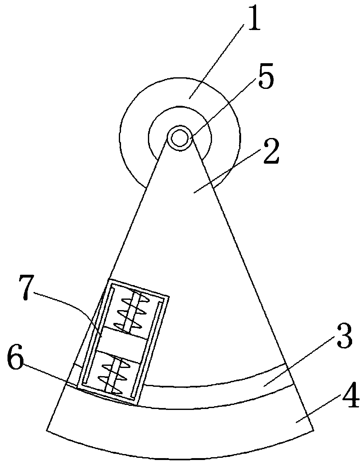
[0039] In this embodiment, further, as Figure 5 , the swing connector 2 is a fan-shaped plate, and is arranged with the rotor output shaft of the generator 1 as the axis, and the pendulum 3 is arc-shaped and fixed to the lower end of the swing connector 2 by welding.
[0040] In order to realize the switching between wave energy generation and wind energy generation, further, an adjustment device 8 is included, and the adjustment device 8 is arranged between the swing connecting piece 2 and the one-way bearing 5 . The concrete structure of regulating device 8 is as follows:
[0041] The adjusting device 8 includes a fixing seat 81, an adjusting screw 82 and a lock nut 83. The fixing seat 81 is sleeved on the one-way bearing 5, and the upper end of the swing connector 2 is fixed with an adjusting screw 82. The upper end of the adjusting screw 82 is threadedly connected with the fixing base 81 , and the adjusting screw 82 is provided with a locking nut 83 . Adjusting screw 82...
PUM
 Abstract
Description
Claims
Application Information