Blade root pre-buried connection structure of wind power electricity generation composite material blade and wind power generation equipment

A technology of composite materials and connection structures, which is applied in wind power generation, wind engines, mechanical equipment, etc., can solve problems such as low stiffness of connected parts, burnt composite materials, and poor mechanical properties, so as to increase the contact area and improve Fatigue life, effect of reducing equivalent stiffness

Active Publication Date: 2019-02-01
ZHUZHOU TIMES NEW MATERIALS TECH
View PDF5 Cites 3 Cited by
  • Summary
  • Abstract
  • Description
  • Claims
  • Application Information

AI Technical Summary

Problems solved by technology

In order to ensure the flatness of the end surface of the embedded bolt sleeve of the blade root, when the end surface is ground, the end surface of the embedded bolt sleeve of the blade root near the mold clamping joint has not been polished, and the end surface of the embedded bolt sleeve of the blade root at other positions has been polished. It is flush with the composite material of the blade root; when the high-speed metal grinder touches the composite material, high-speed friction generates heat, and the composite material is easily burned, resulting in poor mechanical properties
[0005] (2) The area of ​​the end surface of the embedded bolt sleeve of the blade root is small, and when it contacts the end surface of the flange, the rigidity of the connected parts is small, a

Method used


Image

  • Blade root pre-buried connection structure of wind power electricity generation composite material blade and wind power generation equipment
  • Blade root pre-buried connection structure of wind power electricity generation composite material blade and wind power generation equipment

Examples


Embodiment Construction

[0022] The following description serves to disclose the present invention to enable those skilled in the art to carry out the present invention. The preferred embodiments described below are only examples, and those skilled in the art can devise other obvious variations. Directional terms such as "front", "rear", "left" and "right" in the following description are not to be construed as limiting the present invention. The basic principles of the present invention defined in the following description can be applied to other embodiments, variations, improvements, equivalents and other technical solutions without departing from the spirit and scope of the present invention.

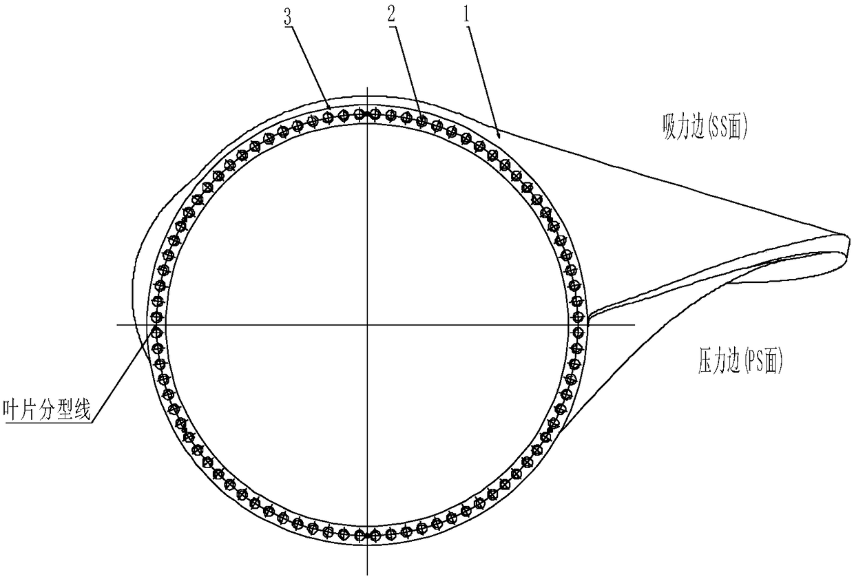
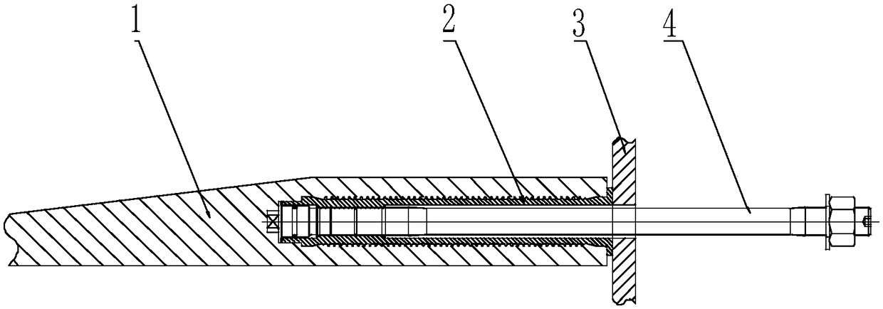
[0023] The following is a further detailed description of a wind power composite blade root embedded connection structure provided by the present invention in conjunction with the accompanying drawings:

[0024] Such as Figure 1-2 As shown, a wind power composite blade root embedded connection structure p...


PUM


Abstract

The invention discloses a blade root pre-buried connection structure of a wind power electricity generation composite material blade and wind power generation equipment. The blade root pre-buried connection structure of the wind power electricity generation composite material blade comprises a blade root, a blade root pre-buried bolt sleeve and a blade root flange; the blade root pre-buried bolt sleeve comprises a bolt sleeve body and a flange, the flange is located on the end portion of the blade root pre-buried bolt sleeve, the blade root pre-buried bolt sleeve is pre-buried in the hole, matched with the blade root pre-buried bolt sleeve, in the blade root, and the flange protrudes out of the end portion of the blade root; and the blade root is in contact with the surface, close to one side of the bolt sleeve body, of the flange, and the blade root flange is in contact with the surface, away from one side of the bolt sleeve body, of the flange. According to the blade root pre-buriedconnection structure of the wind power electricity generation composite material blade and the wind power generation equipment, not only can the fatigue life and stability of a connecting bolt be improved, but also the production technology of the blade is further optimized, a composite material is prevented from being burned and deteriorated caused by friction heat when the blade root is subjected to grinding, and the production technology is easier to control.

Description

technical field [0001] The invention relates to the field of composite material blades of wind power generating sets, in particular to a pre-embedded connection structure of wind power composite material blade roots. Background technique [0002] There are usually two ways to connect the blade root of the wind turbine blade and the pitch bearing: the T-shaped punching type and the pre-embedded blade root bolt sleeve type. As the length of the blade increases, the megawatt level of the wind power generation unit increases, and the load on the blade also increases. More connecting bolts are arranged at the blade root to ensure sufficient ultimate strength and fatigue strength of the blade root connecting bolts. [0003] The existing pre-embedded structure of wind turbine blade root has the following disadvantages: [0004] (1) In order to facilitate the grinding of high-speed metal grinders, the blade root embedded bolt sleeve generally protrudes from the end face of the bla...

Claims


Application Information

Patent Timeline
IPC IPC(8): F03D80/00
CPCF03D80/00F05B2240/21F05B2240/30Y02E10/72Y02P70/50
Inventor 侯彬彬张文伟刘鹏辉赵建刚邓航靳交通周萍马宝宁帅志宏吴方贺
Owner ZHUZHOU TIMES NEW MATERIALS TECH
Why Eureka
Try Eureka