A damping type pilot control switch valve

A pilot control and damping technology, which is applied in the direction of servo motor components, mechanical equipment, fluid pressure actuators, etc., can solve the problems of increasing complexity, increasing the volume of switching valves, and reducing reliability.

Active Publication Date: 2020-10-27
福建禹工阀业有限公司
View PDF5 Cites 0 Cited by
  • Summary
  • Abstract
  • Description
  • Claims
  • Application Information

AI Technical Summary

Problems solved by technology

For fluid control valves with medium and large flow rates, since the hydraulic force acting on the valve core is too large when the valve core is opened, it is still impossible to overcome the hydraulic force to push the valve core simply by increasing the volume of the electromagnetic drive device.
So the current technology is: use a small electromagnetic switch valve (usually 6-way through) as the pilot stage, control the pressure of the left and right chambers of the valve core, and realize the hydraulic power to push the valve core, which solves the problem of large flow down-changing However, this technology not only increases the volume of the switch valve, but also increases the cost. The superposition of the two valves also increases the complexity of the valve and reduces the reliability of the valve.

Method used


Image

  • A damping type pilot control switch valve
  • A damping type pilot control switch valve
  • A damping type pilot control switch valve

Examples


Embodiment 1

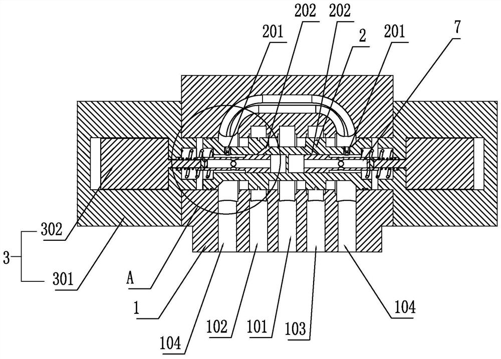
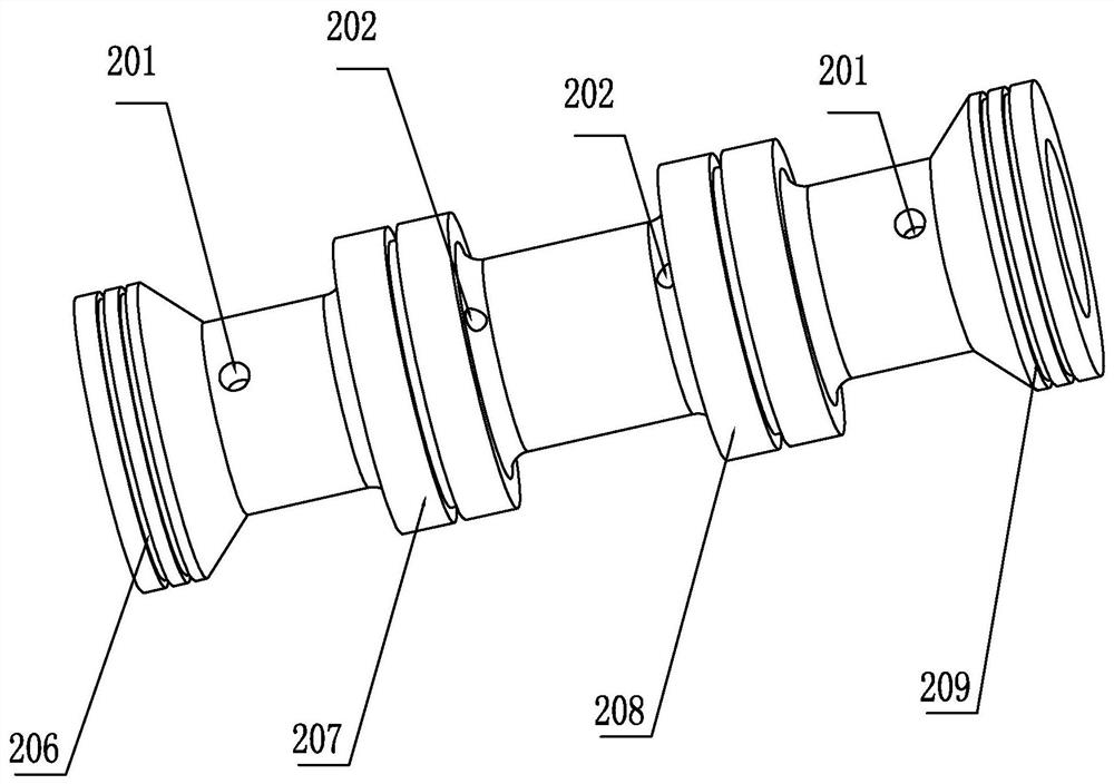
[0035] like figure 1As shown, a damping type pilot control switch valve includes a valve body 1 and a main valve core 2. The valve body 1 is provided with a high-pressure oil inlet 101, a first control oil port 102, a second control oil port 103, Two low-pressure oil outlets 104 (can be 0 pressure), two low-pressure oil outlets 104 are set on both sides, high-pressure oil inlet 101 is set in the middle, and the first control oil port 102 and the second control oil port 103 are respectively set Between the two low-pressure oil outlets 104 and the high-pressure oil inlet 101, such as figure 2 As shown, the main valve core 2 is provided with a first protruding ring 206, a second protruding ring 207, a third protruding ring 208, and a fourth protruding ring 209 in the circumferential direction, and the first protruding ring 206 and the fourth protruding ring 209 are respectively located at The two ends of the main spool 2 are in dynamic sealing cooperation with the valve body 1 ...

Embodiment 2

[0048] Such as Figure 5 As shown, a damping type pilot control switch valve includes a valve body 1 and a main valve core 2. The valve body 1 is provided with a high-pressure oil inlet 101, a first control oil port 102, a second control oil port 103, Two low-pressure oil outlets 104 (can be 0 pressure), two low-pressure oil outlets 104 are set on both sides, high-pressure oil inlet 101 is set in the middle, and the first control oil port 102 and the second control oil port 103 are respectively set Between the two low-pressure oil outlets 104 and the high-pressure oil inlet 101, the main valve core 2 is provided with a first protruding ring 206, a second protruding ring 207, a third protruding ring 208, and a fourth protruding ring 209 in the circumferential direction. The first protruding ring 206 and the fourth protruding ring 209 are respectively located at both ends of the main valve core 2 and are in dynamic sealing cooperation with the valve body 1 (the sealing performan...

Embodiment 3

[0057] Such as Figure 8 As shown, an inflow damping type pilot control on-off valve includes a valve body 1 and a main valve core 2. The valve body 1 is provided with a high-pressure oil inlet 101, a first control oil port 102, and a second control oil port. 103. Two low-pressure oil outlets 104 (can be 0 pressure), two low-pressure oil outlets 104 are set on both sides, high-pressure oil inlet 101 is set in the middle, the first control oil port 102, the second control oil port 103 respectively arranged between the two low-pressure oil outlets 104 and the high-pressure oil inlet 101, such as figure 2 As shown, the main valve core 2 is provided with a first protruding ring 206, a second protruding ring 207, a third protruding ring 208, and a fourth protruding ring 209 in the circumferential direction, and the first protruding ring 206 and the fourth protruding ring 209 are respectively located at The two ends of the main spool 2 are in dynamic sealing cooperation with the v...


PUM


Abstract

The invention belongs to the field of fluid drive and control, in particular relates to a damping type pilot control switch valve. The damping type pilot control switch valve comprises a valve body and a main valve element. The two ends of the valve body are respectively provided with a driving device. An adjusting cavity is formed between the driving device and the main valve element. Two open grooves are arranged in the two ends of the main valve element. Pilot valve elements are arranged in the two open grooves. The adjusting cavity is communicated with a low-pressure oil outlet or a high-pressure oil inlet through fixed damping. The pilot valve elements is driven to enable the adjusting cavity to be communicated with or not communicated with the high-pressure oil inlet or the low-pressure oil outlet, so that a hydraulic acting force is formed, thereby moving the main valve element. The damping type pilot control switch valve has the advantages 1 that the main valve element is driven by hydraulic acting force instead of direct electromagnetic driving, so as to greatly increase the driving force; 2 that the pilot valve element is designed inside the main valve element, so as to greatly reduce the volume; 3 that the pilot valve element is designed for controlling the pressure of the control cavity at the two ends of the main valve, and the flow required by the pilot control isvery small, so that the driving force of driving the pilot valve element can be very small, the size of the electromagnetic driving device is further reduced, and the purposes of energy conservationand emission reduction are achieved.

Description

technical field [0001] The invention belongs to the field of fluid transmission and control, and in particular relates to a damping type pilot control switch valve. Background technique [0002] Fluid control valves, especially hydraulic valves, play the role of controlling flow, pressure and switching oil circuits. For example, the electromagnetic switching valve plays the role of controlling the flow and switching the oil circuit; the electromagnetic switching valve is divided into: single-stage valve (direct acting valve) and two-stage valve (pilot control valve) according to the flow capacity. In the industry standard, single-stage valves (direct-acting valves) are divided into 6 channels and 10 channels; two-stage valves (pilot control valves) are divided into 16, 25, 32... channels (the larger the number The larger the valve volume, the greater the flow capacity). [0003] The fluid switching control valve used for small flow is generally in the form of a single-stag...

Claims


Application Information

Patent Timeline
Patent Type & Authority Patents(China)
IPC IPC(8): F15B13/02
CPCF15B13/021
Inventor 任燕汤何胜向家伟周余庆钟永腾蒋勇英孙维方
Owner 福建禹工阀业有限公司
Why Eureka
Try Eureka