Water tank heating equipment

A technology for heating equipment and water tanks, applied in lighting and heating equipment, water heaters, fluid heaters, etc., can solve problems such as electric leakage of heating rods, life-threatening, and prone to electric shocks, and reduce the possibility of electric leakage. The effect of improving safety and improving electricity safety

Pending Publication Date: 2019-02-01
浙江英展电器有限公司
View PDF0 Cites 0 Cited by
  • Summary
  • Abstract
  • Description
  • Claims
  • Application Information

AI Technical Summary

Problems solved by technology

[0004] As in the above-mentioned disclosed technology, since the heating rod needs to be put into the water, the heating rod is in direct contact with the water body and the heating rod is connected to the electric control terminal, so that the heating rod is charged. When the heating rod is aging or has quality problems, it is very easy to cause leakage. It makes the heated water body electrified. When the human body touches the water body, it is very easy to get an electric shock and cause life danger. There are deficiencies that need to be improved.

Method used


Image

  • Water tank heating equipment
  • Water tank heating equipment
  • Water tank heating equipment

Examples


Embodiment 1

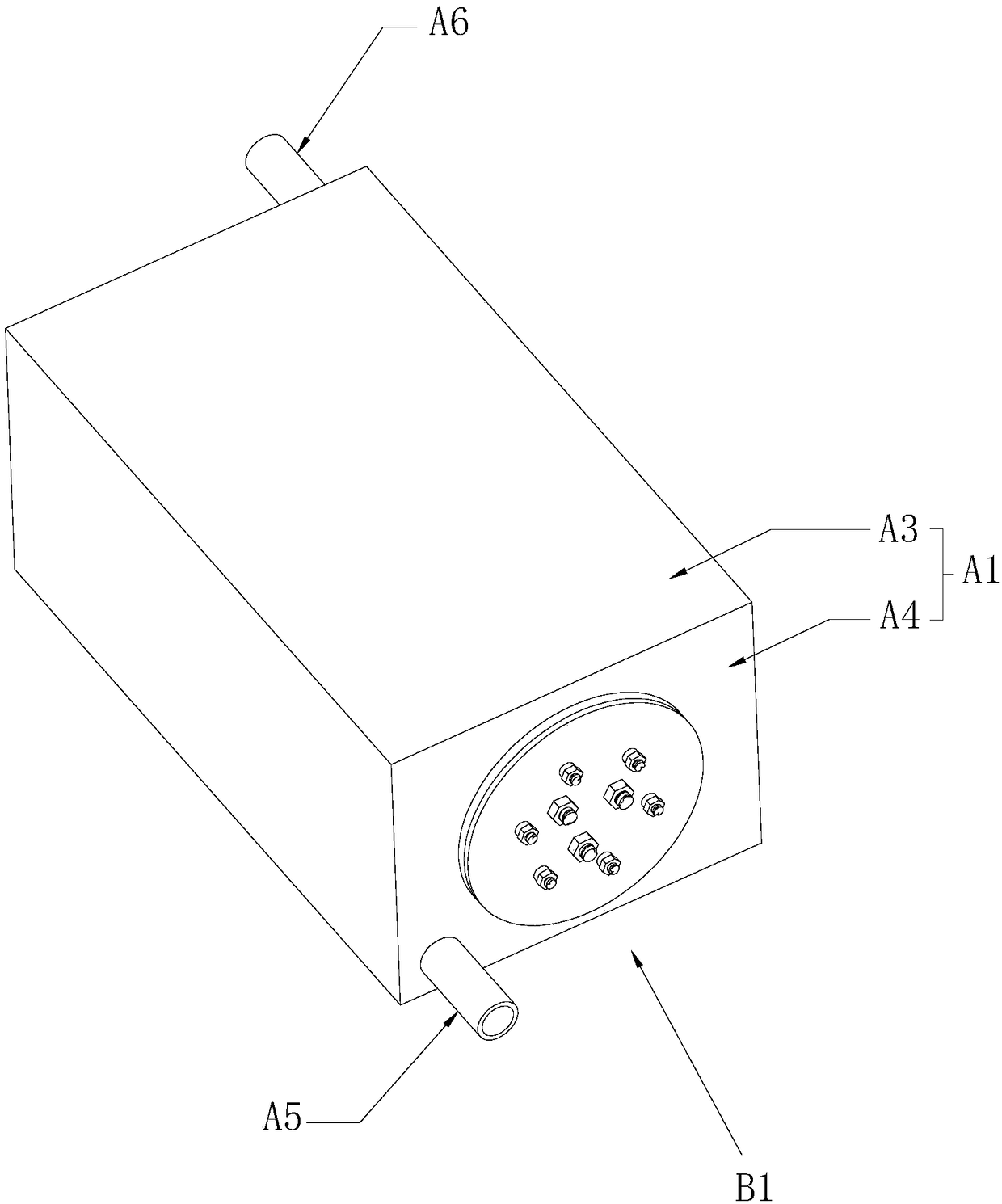
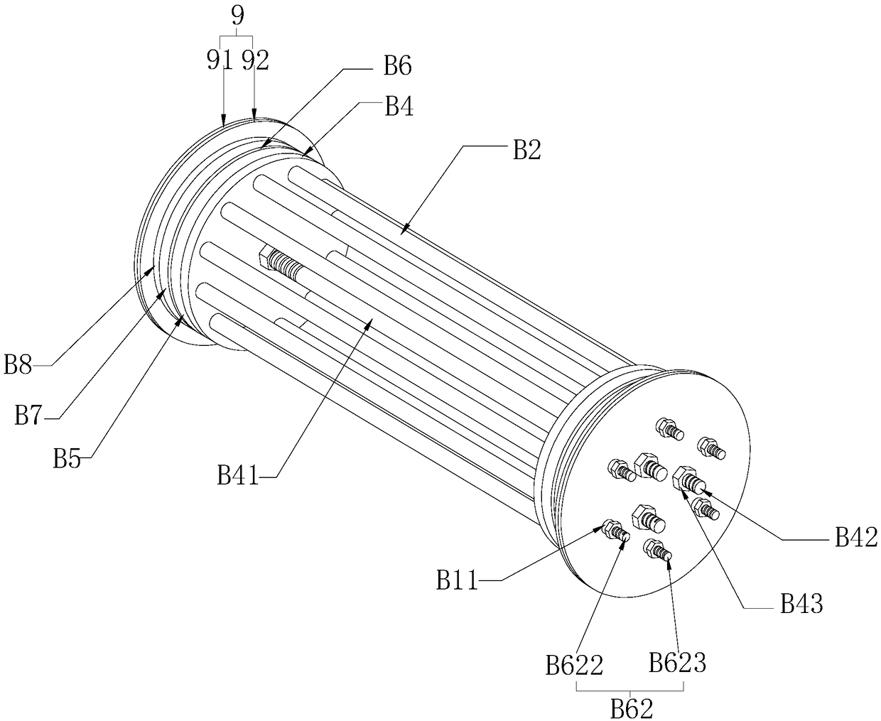
[0041] Such as figure 1 and image 3 As shown, a water tank heating device includes a box body A1 and a heating unit B1 arranged in the box body A1. The box body A1 is provided with an inner cavity A7 and an outer cavity A8. The water inlet pipe A5 and the water outlet pipe A6 connected to the cavity A8, the heating unit B1 includes the glass tube B2 and the heating wire B3, the glass tube B2 is fixed in the inner cavity A7, the heating wire B3 is penetrated in the glass tube B2, and the glass tube B2 supports The heating wire B3 also blocks the short circuit between the heating wires B3, and a sealing unit is provided between the two ends of the glass tube B2 and the box body A1.

[0042] Connect the heating wire B3 to the power supply, and pass water into the body of the outer cavity A8 through the water inlet pipe A5, and the heating wire B3 generates thermal radiation to increase the temperature of the water in the body of the outer cavity A8, thereby achieving the purpos...

Embodiment 2

[0053] The difference between embodiment two and embodiment one lies in:

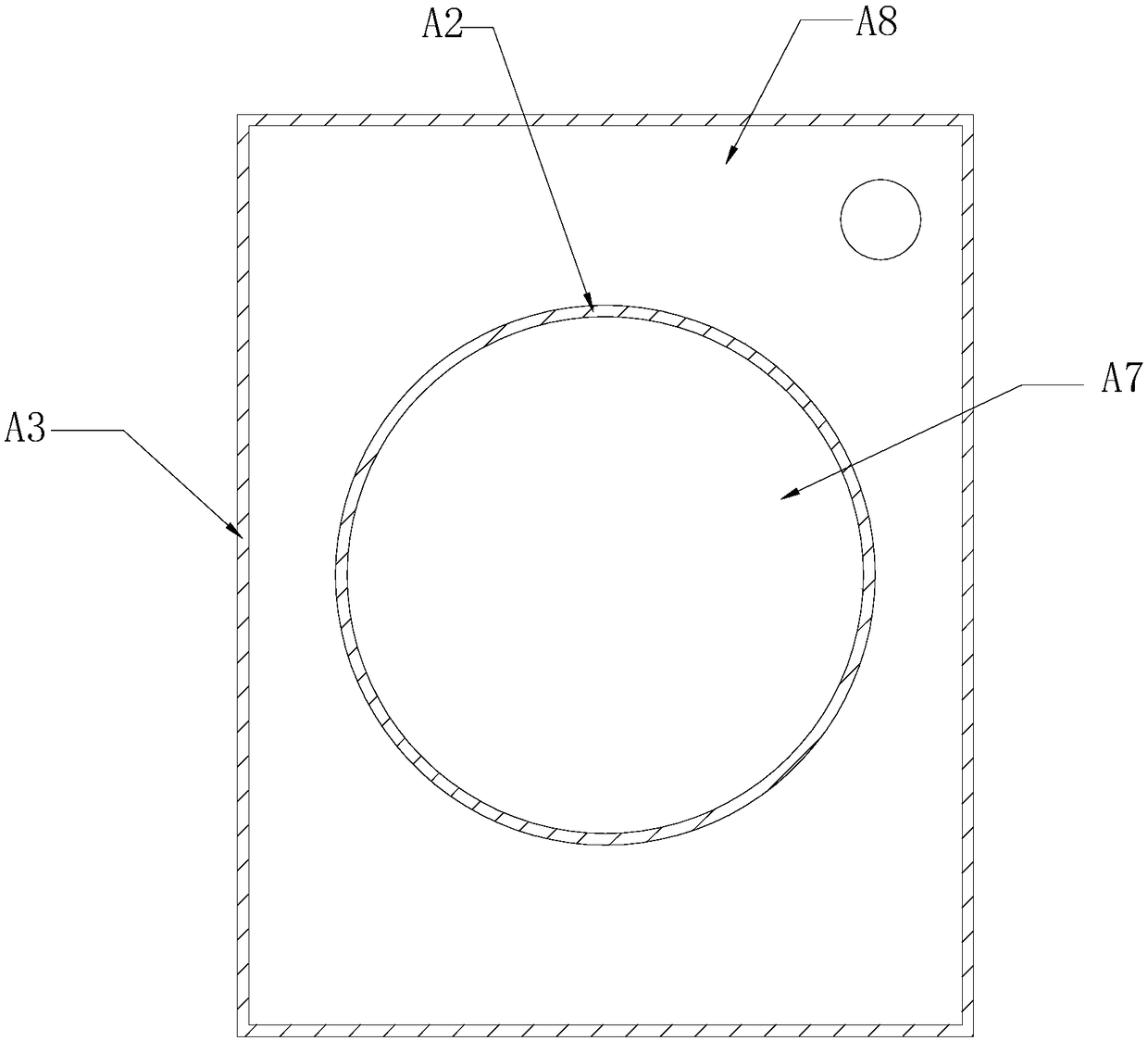
[0054] Such as Figure 6 As shown, the outer liner A3 is arranged in a cylindrical shape, and the outer liner A3 and the inner liner A2 are arranged coaxially, so that the outer cavity A8 is cylindrical, and the inner liner A2 faces the side of the outer liner A3 The spiral drainage plate A9 is provided to increase the flow path of the water body in the outer cavity A8; when the heating area B10 is not fully energized, the water flow can pass through the energized heating area B10 to ensure the heating of the water body and avoid freezing in the water body conditions, and when the temperature difference is greater, the heat absorption efficiency is higher, and the water body with a lower temperature can still pass through the electrified heating zone B10, improving the heat energy absorption efficiency and utilization rate.

[0055] And there is a thermal insulation gap A91 between the spiral drainage ...


PUM


Abstract

The invention relates to heating equipment, and discloses a water tank heating equipment. The water tank heating equipment comprises a box body, a glass tube and an electric heating wire, the box bodycomprises an inner cavity which is used for penetrating through the glass tube and an outer cavity which is used for communicating water, the two opposite ends of the glass tube are provided with supporting plates respectively, the outer periphery of the supporting plate abuts against the inner cavity, and an inserting hole for inserting the glass tube is formed in the supporting plate; supporting column is connected between the supporting plates, connecting columns extend from one end, opposite to the back of the supporting plates, of the supporting plates, the two opposite ends of the innercavity are provided with fixing plates abutting against the box body, the connecting columns penetrate through the fixing plates, and the connecting column is in threaded connection with locking nutsabutting against the fixing plates; and each fixing plate comprises a steel plate and an insulation plate II, and the insulation plate II is abutted against the box body. According to the water tankheating equipment, the glass tube and the electric heating wire are arranged in the inner cavity of the box body, the water flow flows in the outer cavity of the box body, so that the purpose of waterand electricity separation is achieved, an insulation structure is arranged between the glass tube and the box body, so that the electricity utilization safety of equipment is greatly improved.

Description

technical field [0001] The invention relates to the field of heating, in particular to a water tank heating device. Background technique [0002] Existing heating methods include heat convection, heat radiation, and heat conduction. Heat convection refers to the heat transfer process caused by the relative displacement of the particles in the fluid; heat radiation refers to the phenomenon that the object radiates electromagnetic waves due to its temperature; heat conduction refers to the heat transfer phenomenon when there is no macroscopic motion in the medium. Can occur in gas. [0003] Most of the existing hot water heating adopts the fast heat, which includes the heating rod and the electric control terminal. After the electric control terminal is connected to the electricity, the heating rod is heated, and the heating rod is put into the water to make the heat on the heating rod Transfer directly to the water to achieve the purpose of water heating. [0004] As in th...

Claims


Application Information

Patent Timeline
IPC IPC(8): F24H1/20F24H9/18F24H9/20
CPCF24H1/183F24H1/202F24H9/1818F24H9/2021
Inventor 刘生财郑庆祥李超王强
Owner 浙江英展电器有限公司
Why Eureka
Try Eureka