Thermal-structure coupling loading method for large-size disc brake

A disc brake, thermal structure technology, applied in instruments, special data processing applications, electrical digital data processing, etc., can solve the problems of complex assumptions, small size, large size of brake components, etc.

Pending Publication Date: 2019-02-01
CRRC QINGDAO SIFANG ROLLING STOCK RES INST
View PDF2 Cites 5 Cited by
  • Summary
  • Abstract
  • Description
  • Claims
  • Application Information

AI Technical Summary

Problems solved by technology

At present, the existing thermal-structural coupling method selects a small research object, and often ignores the radial difference in linear velocity due to the width of the brake disc / brake pad and its influence, and directly loads the frictional heat flow evenly on the brake brake. a
However, the size of the braking element in the basic braking device of high-speed rail vehicles is relatively large, and the radial difference in the width of the brake disc / brake pad and the linear velocity under the influence of it are obvious; at the same time, the disc brake is The thermal effect of the braking process is more complex than the assumed working conditions of the existing thermal-structure coupling method. In the direction of rotation of the brake disc, the non-contact area with the brake pad is much larger than the contact area at the same time, which will also cause relatively large friction during the braking process. large temperature gradient
[0004] For the thermal-structural coupling analysis of large-size disc brakes used in high-speed and heavy-load conditions, the current thermal-structural coupling method cannot effectively simulate the transient distribution of temperature field, stress and deformation under this condition. This will cause difficulties in material selection and structural optimization in the design process of the brake, affect the service life of the brake product, and even leave a safety hazard in the process of product use

Method used


Image

  • Thermal-structure coupling loading method for large-size disc brake
  • Thermal-structure coupling loading method for large-size disc brake
  • Thermal-structure coupling loading method for large-size disc brake

Examples


Embodiment Construction

[0072] Specific embodiments of the present invention will be further described below in conjunction with the accompanying drawings.

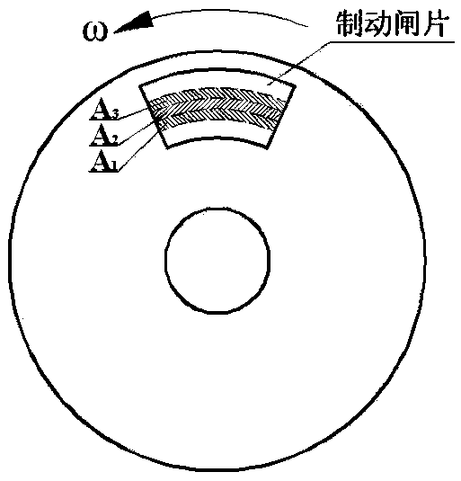
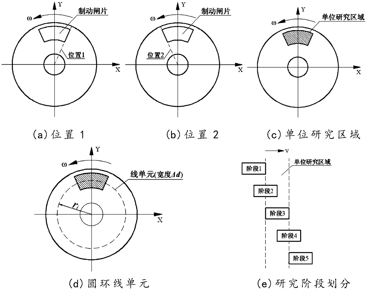
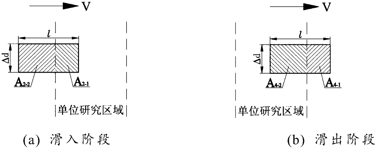
[0073] The invention provides a large-size disc brake thermal structure coupling loading method, which can be applied to the design of rail vehicle brakes, and is a displacement gradient iteration method. The displacement gradient iterative method selects two dimensions to divide the research area by the displacement gradient, namely along the radial direction (radial direction) of the brake disc and along the rotational direction (circumferential direction) of the brake disc, and divides the circulation of each research area Iteratively load the internal frictional heat flow, so that the thermal-structural coupling model can accurately reflect the transient distribution trend of each physical field.

[0074] According to the actual working conditions of rail trains, the following assumptions are made: (1) Assume that the brake disc rotates coun...


PUM


Abstract

The invention relates to a large-size disc brake thermal structure coupling loading method. The thermal structure coupling loading method is a displacement gradient iterative method, comprising a friction heat flux radial loading method and a friction heat flux circumferential loading method. That is to say, the friction heat flux generated in the cycle of each research area is loaded iterativelyalong the radial and circumferential directions of the brake disc respectively. Displacement gradient iterative method can be used to solve the problem of friction heat flux loading caused by the width of left and right area of large brake disc/brake pad and the radial difference of linear velocity under the influence of the width, and the temperature gradient produced alternately by contact surface and non-contact surface can not reflect the problem of thermal structure coupling model. The transient distribution of temperature field, stress field and deformation in all directions on the surface of brake disc can be solved accurately, which provides theoretical support for the optimization of large size brake disc design under complex working conditions.

Description

technical field [0001] The invention belongs to the technical field of thermal structure coupling of rail vehicle disc brakes, and in particular relates to a thermal structure coupling loading method of a large-size disc brake. Background technique [0002] Disc brakes are widely used in high-end equipment such as modern rail vehicles and large wind turbines. They are also the most important actuator components in the basic braking devices of high-speed rail vehicles, and have a direct impact on the braking performance of trains. During the braking process, when the brake pads are in contact with the brake disc, they are jointly affected by the braking pressure and frictional resistance, and the frictional resistance does work to generate a large amount of heat energy. Due to the inhomogeneous contact of the friction pair during the braking process, the actual contact area is smaller than the ideal contact area and is in discontinuous contact, which will aggravate the uneven...

Claims


Application Information

Patent Timeline
Patent Type & Authority Applications(China)
IPC IPC(8): G06F17/50
CPCG06F30/23
Inventor 刘楠金星侯丹王炳坤王飞
Owner CRRC QINGDAO SIFANG ROLLING STOCK RES INST
Why Eureka
Try Eureka