Wireless charging coil

A wireless charging and coil technology, which is applied in the direction of transformer/inductor coil/winding/connection, circuit, inductor, etc., can solve the problems of reduced coil transmission efficiency, easy deviation, and difficult alignment of transmitting coils. Achieve the effect of reducing energy transfer efficiency and negative impact of power

Pending Publication Date: 2019-02-01
上海奕征新能源技术有限公司
View PDF0 Cites 6 Cited by
  • Summary
  • Abstract
  • Description
  • Claims
  • Application Information

AI Technical Summary

Problems solved by technology

During the parking and charging process of electric vehicles, the receiving coil installed on the chassis of the car and the transmitting coil laid undergrou

Method used


Image

  • Wireless charging coil
  • Wireless charging coil
  • Wireless charging coil

Examples


Embodiment Construction

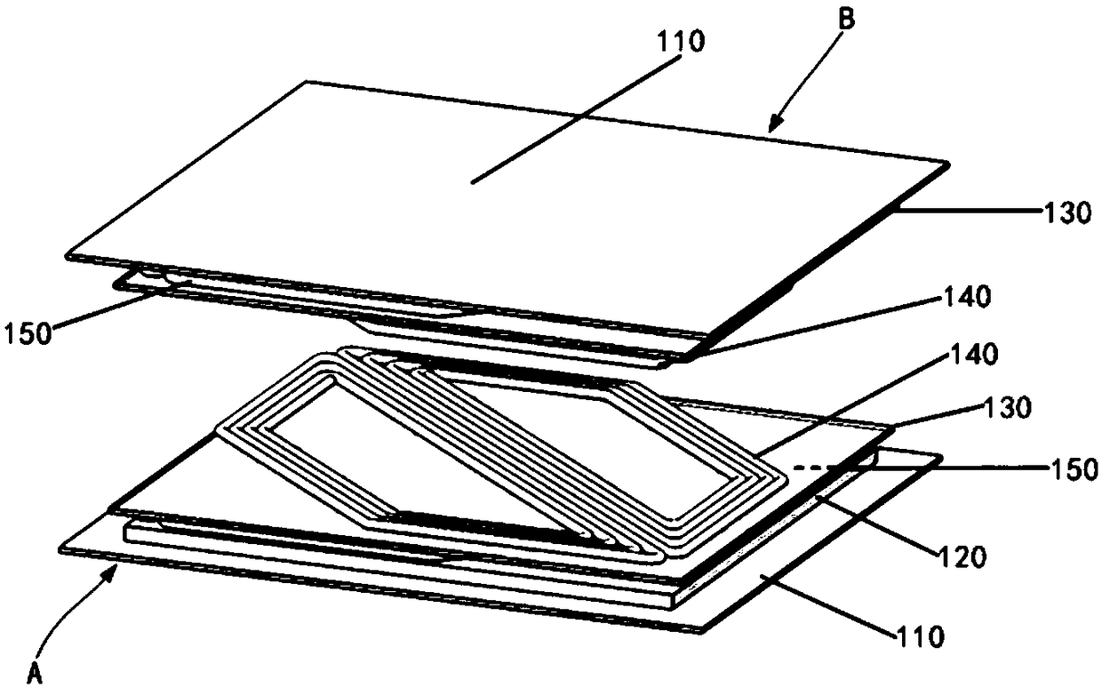
[0017] like figure 1 As shown, a wireless charging coil includes a transmitting end A and a receiving end B coupled to realize energy wireless transmission.

[0018] like figure 1 As shown, both the transmitting end A and the receiving end B include a magnetic shielding layer 110 , a magnetic medium layer 120 , a coil support layer 130 , and a first coil layer 140 and a second coil layer 150 connected in series.

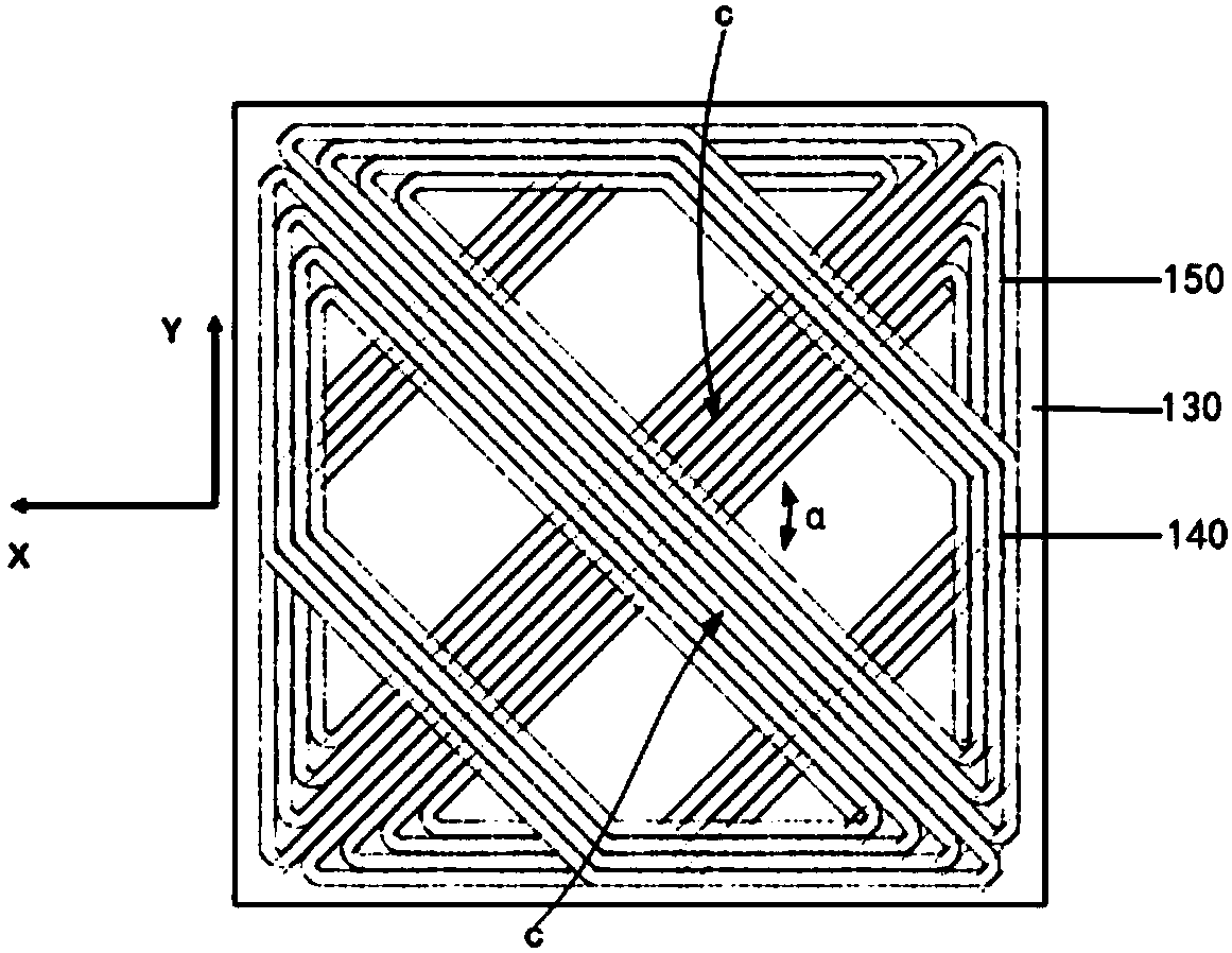
[0019] The first coil layer 140 and the second coil layer 150 are respectively fixed on the front and back sides of the coil support layer 130. The shapes of the first coil layer 140 and the second coil layer 150 are the same, and both take the center line of the coil support layer 130 as the axis. Form a deflection angle α greater than 0° and less than 360°, see image 3 , so that the magnetic fields generated by the first coil layer 140 and the second coil layer 150 form a corresponding angle, which can effectively reduce the negative impact of the positive devia...


PUM


Abstract

The invention discloses a wireless charging coil. The wireless charging coil comprises an emitting end and a receiving end, the emitting end and the receiving end realize energy wireless transmissionthrough coupling, and separately comprise a magnetic shielding layer, a magnetic medium layer, a coil supporting layer, a first coil layer and a second coil layer, the first coil layers and the secondcoil layers are mutually connected in series and fixed to the front faces and the rear faces of the coil supporting layers respectively, the shapes of the first coil layers and the second coil layersare identical, and the first coil layers and the second coil layers form a deflection angle alpha which is larger than 0 degree and smaller than 360 degrees with the center lines of the coil supporting layers being axes. The first coil layers and the second coil layers of the wireless charging coil are fixed to the front faces and the rear faces of the coil supporting layers respectively to formthe deflection angle, magnetic fields generated by the first coil layers and a magnetic field generated by the second coil layers form a corresponding angle, and therefore negative influences of coilaligning deviation on energy transmission efficiency and power can be effectively reduced.

Description

technical field [0001] The invention belongs to the technical field of wireless charging, and in particular relates to a wireless charging coil. Background technique [0002] As an emerging charging technology, wireless power transfer technology refers to the use of electromagnetic fields to achieve long-distance transmission of energy without physical contact. Due to its strong applicability, wireless charging technology has been widely used in many fields, and one of the main application fields is electric vehicles. Compared with the traditional charging method using charging piles for wired charging, the application of wireless charging technology in electric vehicles has the advantages of convenient use, high safety, no environmental impact, and no space resources, which can effectively promote the development of electric vehicles. popularity. By laying the coil transmitter underground and fixing the coil receiver on the chassis of the electric vehicle, the driver only...

Claims


Application Information

Patent Timeline
IPC IPC(8): H01F27/28H01F27/36H01F38/14H02J50/10H02J50/70
CPCH02J50/10H02J50/70H01F27/28H01F38/14H01F27/36
Inventor 张希
Owner 上海奕征新能源技术有限公司
Why Eureka
Try Eureka