Insulation and heat conduction heat radiation structure based on ceramic chip

A technology of insulating heat conduction and heat dissipation structure, which is applied in the direction of semiconductor devices, semiconductor/solid-state device components, electrical components, etc., can solve the problems of low dielectric strength, IGBT enhanced dielectric strength, etc., and achieve the effect of enhancing insulation performance

Pending Publication Date: 2019-02-01
重庆中车四方所智能装备技术有限公司
View PDF0 Cites 4 Cited by
  • Summary
  • Abstract
  • Description
  • Claims
  • Application Information

AI Technical Summary

Problems solved by technology

[0005] Aiming at the deficiencies in the prior art, the present invention provides an insulating, heat-conducting and heat-dissipating structure based on ceramic sheets, which solves the problem of enhancing the dielectric strength of IGBTs with low dielectric strength at low cost

Method used


Image

  • Insulation and heat conduction heat radiation structure based on ceramic chip
  • Insulation and heat conduction heat radiation structure based on ceramic chip
  • Insulation and heat conduction heat radiation structure based on ceramic chip

Examples


Embodiment 2

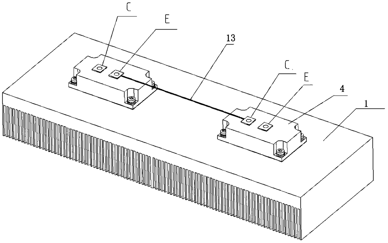
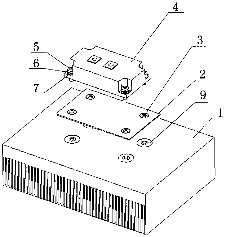
[0032] Such as Figure 3-Figure 6 As shown, an insulating, heat-conducting and heat-dissipating structure based on a ceramic sheet includes a radiator 1, on which an IGBT package 4 is fixed, and an insulating fixture 9; There is a ceramic sheet 2; the insulating fixing member 9 fixes the IGBT package 4 and the ceramic sheet 2 to the heat sink 1 in sequence.

[0033] The IGBT package 4 includes an IGBT substrate 10 disposed at the bottom. The surface of the IGBT substrate 10 in contact with the ceramic sheet 2 is an arcuate surface 14 , and the middle of the arcuate surface 14 protrudes toward the ceramic sheet 2 . In order to increase heat transfer efficiency, a thermally conductive silica gel layer 8 is provided between the IGBT substrate 10 and the ceramic sheet 2 , and between the ceramic sheet 2 and the heat sink 1 .

[0034] The insulating fixing part 9 includes a groove provided on the radiator 1, and a metal screw sleeve 1-3 is arranged in the groove, and a structural ...

Embodiment 3

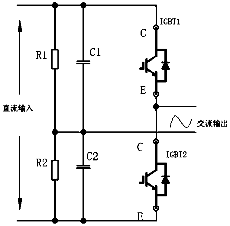
[0041] On the basis of Example 2, the IGBT with a dielectric strength of 1700V is refitted and used, and the dielectric strength between its electrodes (C pole and E pole) and the radiator is determined by the structure of the device itself, that is to say, the electrodes ( The dielectric strength between C pole and E pole) and the radiator is equal to the dielectric strength between the electrodes (C pole and E pole) and the IGBT substrate, and its dielectric strength is generally 4kV. If it is applied to the dielectric strength requirement For lower occasions, there is no problem. However, for some occasions that require high dielectric strength, such as subway charger equipment, the dielectric strength is required to be 5.5kV, which will not be applicable.

[0042] In order to ensure that the IGBT with a dielectric strength of 1700V can meet the higher-level dielectric strength requirements, this solution adds a thermally conductive and insulating ceramic sheet between the ...


PUM


Abstract

The present invention discloses an insulation and heat conduction heat radiation structure based on a ceramic chip. The structure comprises: a radiator (1), wherein an IGBT package piece (4) is fixedon the radiator (1); and an insulation fixed part (9), wherein a ceramic chip (2) is arranged between the radiator (1) and the IGBT package piece (4), the insulation fixed part (9) is configured to fix the IGBT package piece (4) and the ceramic chip (2) at the radiator (1) in order. The ceramic chip with heat conduction and insulation is added between an IGBT electrode and the radiator, and the special insulation fixed part is added at the radiator and the IGBT to enhance the insulation performance between the IGBT electrode and the radiator and meet the application demand with a better dielectric strength; the cost of extra addition of the insulation fixed part on the ceramic chip and the radiator is lower than the cost added by directly selecting a high-level dielectric strength, and therefore, the insulation and heat conduction heat radiation structure based on the ceramic chip has an objective economic benefit.

Description

technical field [0001] The invention relates to the technical field of rail transit traction, in particular to an insulation, heat conduction and heat dissipation structure based on ceramic sheets. Background technique [0002] This application is mainly applied to power modules in rail transit traction and auxiliary products, and the representative application occasion is a charger. The charger is a kind of converter device, which is the core component of the auxiliary system of electric locomotives and subway vehicles. It can provide DC power for the low-voltage DC load of the train and charge it according to the characteristics of the on-board battery. [0003] The important device in the charger module is IGBT, one of which can invert direct current into alternating current through the cooperation of multiple IGBTs. During the working process of IGBT, a large amount of heat will be generated, which needs to be dissipated by a radiator. The general installation structure...

Claims


Application Information

Patent Timeline
Patent Type & Authority Applications(China)
IPC IPC(8): H01L23/367H01L23/373H01L23/40
CPCH01L23/367H01L23/3731H01L23/4006H01L2023/4031H01L2023/405H01L2023/4087
Inventor 薛浩飞徐先伟李国银张星梁鹏谷翠军陈奎
Owner 重庆中车四方所智能装备技术有限公司
Why Eureka
Try Eureka