Beam selection method and equipment

A beam and network equipment technology, applied in advanced technology, network planning, electrical components, etc., can solve problems such as CPE redundancy

Inactive Publication Date: 2019-02-01
HUAWEI TECH CO LTD
View PDF18 Cites 20 Cited by
  • Summary
  • Abstract
  • Description
  • Claims
  • Application Information

AI Technical Summary

Problems solved by technology

But since the location of the CPE is basically fixed, this design is redundant for the CPE

Method used


Image

  • Beam selection method and equipment
  • Beam selection method and equipment
  • Beam selection method and equipment

Examples


Embodiment Construction

[0099] Embodiments of the present application are described below in conjunction with the accompanying drawings.

[0100] Embodiments of the present application can be used in cellular communication systems, mainly for 4G LTE or 5G New Radio (NR) systems, including multiple transmission and reception point (Transmission Reception Point, TRP) scenarios or central unit distributed units (Central Unit- distributed Unit, CU-DU) separation scene.

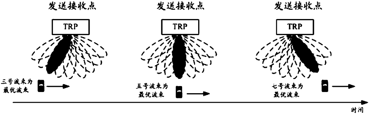
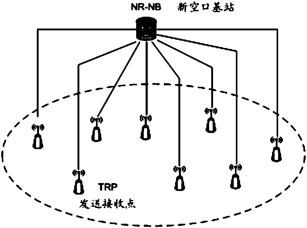
[0101] As an optional application scenario, such as image 3 As shown, under one new air interface base station (NR-NB), there may be one or more TRPs, and each TRP can communicate with a terminal through a beam.

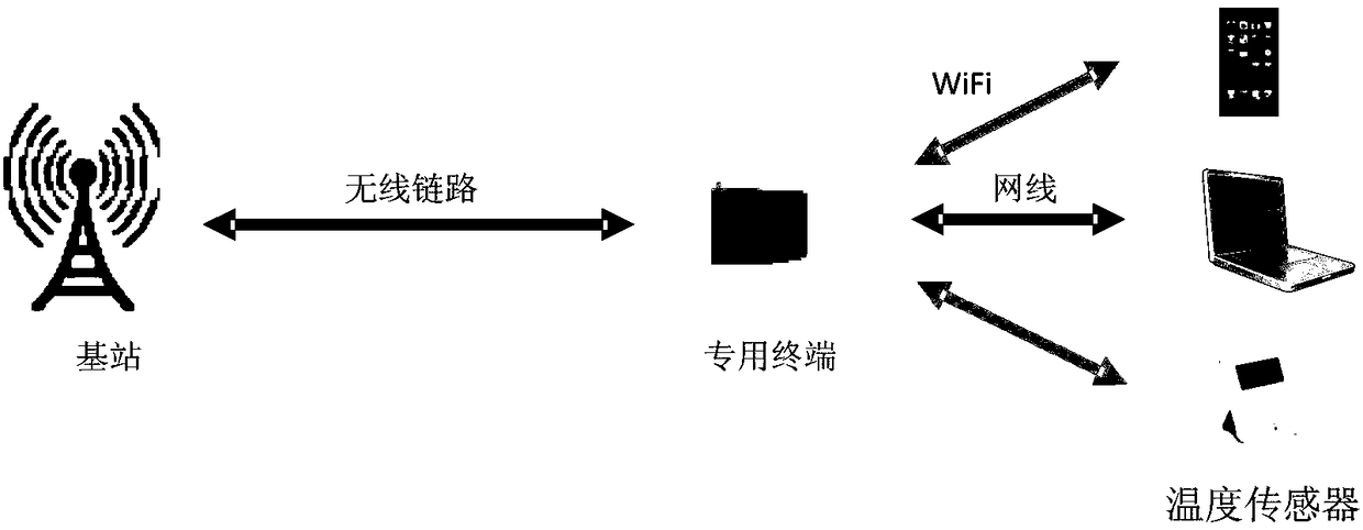
[0102] The network elements involved in this embodiment of the present application include network devices and terminals. Among them, the network device involved in the embodiment of the present application refers to the access device that the terminal accesses to the mobile communication system through wireless means, and m...


PUM


Abstract

The application discloses a beam selection method and equipment. The method comprises the following steps that: a terminal receives first beam configuration information transmitted by first network equipment, wherein the first beam configuration information is used for indicating a service beam, and the service beam is a downlink transmission beam on the side of the first network equipment configured by the first network equipment for the terminal; and the terminal receives downlink data transmitted by the first network equipment through the service beam. Therefore, after the first network equipment configures the service beam for the terminal, the first network equipment transmits downlink scheduling information and data to the terminal through the service beam, so that the terminal no longer needs to monitor scheduling information on other beams, thereby reducing the number of blind detection of the scheduling information and lowering the energy consumption of the terminal.

Description

technical field [0001] The present application relates to the technical field of wireless communication, and in particular to a method and device for selecting a beam. Background technique [0002] With the popularity of optical fiber, more and more families can access the Internet through optical fiber, that is, fiber-to-the-home. Although fiber-to-the-home can provide high-speed data transmission services for families, it also has the disadvantages of high cost and long deployment time. For dense urban areas, the user density is high, and the deployment cost can be shared, but for remote areas, the population is sparse, and the number of households needs to support high fiber costs. At the same time, the deployment of optical fibers requires trenching and embedding, and there are certain requirements for the deployment terrain, and some protected buildings may not allow construction. Therefore, in general, the fiber-to-the-home method has the characteristics of high spee...

Claims


Application Information

Patent Timeline
Patent Type & Authority Applications(China)
IPC IPC(8): H04W24/08H04W52/02H04W72/04
CPCH04W24/08H04W52/0225H04W72/046H04W72/23H04W52/02H04W72/04H04W24/10Y02D30/70H04W16/28
Inventor 唐珣权威张戬
Owner HUAWEI TECH CO LTD
Why Eureka
Try Eureka