Hull bottom arthropod type suction grille

A technology of suction grilles and joints, which is applied to ship parts, ship construction, ships, etc., can solve the problems of lack of versatility, debris entering, and increased workload of workers, and achieve the effect of improving overall stability and versatility

Active Publication Date: 2019-02-05
天长市蓝天船舶设备制造有限公司
View PDF7 Cites 2 Cited by
  • Summary
  • Abstract
  • Description
  • Claims
  • Application Information

AI Technical Summary

Problems solved by technology

[0003] It is customary to make the bottom suction grille in the form of a straight plate on ships or offshore platforms. According to the usual practice, if the line shape of the hull plate where the bottom suction grille is located is relatively tortuous or the length-width ratio of the seabed grille is large, the bottom suction grille and There will be a large flash seam between the outer plates of the hull. According to the ship registration regulations, such a structure does not meet the requirements. It is necessary to add flash seam adjustment plates on both sides of the hull opening. Due to the narrow space of the seabed valve box, the seabed It is very difficult to add the flash seam adjustment plate in the valve box, which greatly increases the workload of the workers; at the same time, the bottom suction grille with the flash seam adjustment plate lacks aesthetics
[0004] Moreover, the grille plates of the existing bottom suction grille are all integrally formed, and then connected to the fixed frame in the form of hinges. This type of bottom suction grille can only adapt to one size of seawater suction inlet, and needs to be customized according to the size. Lack of versatility, and when the integrated grille is connected by hinges, the gap between the two sides will exceed the standard size, and debris is easy to enter from the gap

Method used


Image

  • Hull bottom arthropod type suction grille
  • Hull bottom arthropod type suction grille
  • Hull bottom arthropod type suction grille

Examples


Embodiment 1

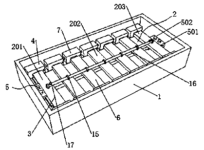
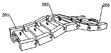
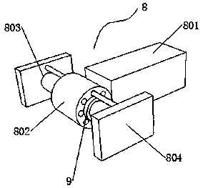
[0044] see Figure 1-9 , a bottom articulated suction grille, comprising a water inlet fixed frame 1, a grille plate group 2 is arranged in the water inlet fixed frame 1, and the grille plate group 2 includes a grille head 201, a grille body 202 and a grille The grid tail part 203, the grid body part 202 includes a plurality of joint grid plates distributed side by side, the joint grid plates include a second grid plate 6 and a pair of second connectors 7, and the joint between a pair of adjacent joint grid plates A connecting mechanism 8 is connected between them. The connecting mechanism 8 includes a fixed part and an active connecting part, which can realize multi-angle connection. The active connecting part includes a connecting rod 801 and a rotating connecting ring 802. The connecting rod 801 is connected to the second connecting head through the rotating connecting ring 802. The left end of 7 is fixedly connected, and the fixed portion includes positioning double rods 8...


PUM


Abstract

The invention discloses a hull bottom arthropod type suction grille, and belongs to the technical field of ship equipment. The hull bottom arthropod type suction grille comprises a water inlet fixingframe, and a grille board group is arranged in the water inlet fixing frame and comprises a grille head part, a grille trunk part and a grille tail part. The grille trunk part comprises a plurality ofarthropod grille boards distributed in parallel, each arthropod grille board comprises a second grille board and a pair of second connecting heads, and a connecting mechanism is connected between each pair of adjacent arthropod grille boards. The connecting mechanisms comprise fixed parts and driving connecting parts, the driving connecting parts comprise connecting rods and rotary connecting rings, the connecting rods are fixedly connected with the left ends of the second connecting heads through the rotary connecting rings, and the fixed parts comprise positioning double rods and operativepull boards. The hull bottom arthropod type suction grille can be subjected to matched adjustment according to ship seawater suction inlets under different situations by imitating the body construction of arthropods, and universality of the hull bottom suction grille is obviously improved from two aspects of size adjustment and line type adjustment.

Description

technical field [0001] The invention relates to the technical field of ship equipment, in particular to a ship bottom articulated suction grille. Background technique [0002] The grid bottom suction grille is the door frame installed on the seawater tank of the ship and used to control the opening and closing of the seawater tank. It is used to filter the sundries mixed in the seawater and prevent the sundries from blocking the fresh water heat exchanger and lubricating oil heat exchanger. , At the same time, it plays a very important role in preventing sundries from winding the cooling water pump, etc. [0003] It is customary to make the bottom suction grille in the form of a straight plate on ships or offshore platforms. According to the usual practice, if the line shape of the hull plate where the bottom suction grille is located is relatively tortuous or the length-width ratio of the seabed grille is large, the bottom suction grille and There will be a large flash sea...

Claims


Application Information

Patent Timeline
Patent Type & Authority Applications(China)
IPC IPC(8): B63B17/00
Inventor 李贻飞
Owner 天长市蓝天船舶设备制造有限公司
Why Eureka
Try Eureka