Cross-shaped shaft grinding and clamping device

A technology of clamping device and cross shaft, applied in the direction of grinding drive device, grinding/polishing safety device, grinding frame, etc., can solve the problems of time-consuming and laborious, affecting work efficiency, etc., and achieve good cleaning effect and positioning effect. Good, the effect of improving the utilization rate of gas

Active Publication Date: 2019-02-12
宁波隆锐机械制造有限公司
View PDF8 Cites 5 Cited by
  • Summary
  • Abstract
  • Description
  • Claims
  • Application Information

AI Technical Summary

Problems solved by technology

Therefore, the grinding of the cross shaft needs a clamping device to fix it, and the current clamping device for grinding the cross shaft is to fix one of the shafts in the cross shaft first, and then perform the grinding process, and then perform manual grinding after the grinding is completed. It is time-consuming and labor-intensive to replace a single axis manually after the grinding process is completed, because the cross axis has four axes, which will affect the work efficiency. In view of the above defects, it is necessary to design a cross axis Shaft Grinding Clamping Device

Method used


Image

  • Cross-shaped shaft grinding and clamping device
  • Cross-shaped shaft grinding and clamping device
  • Cross-shaped shaft grinding and clamping device

Examples


Embodiment Construction

[0024] The following is further described in detail through specific implementation methods:

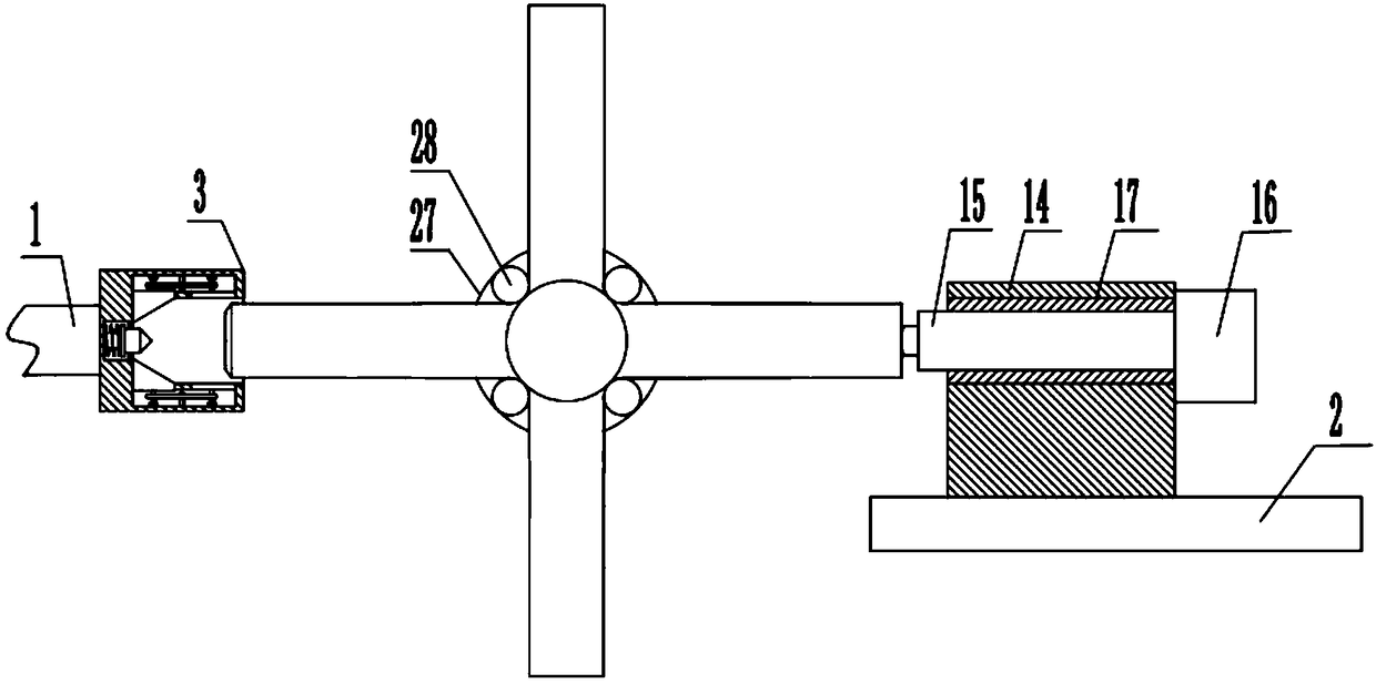
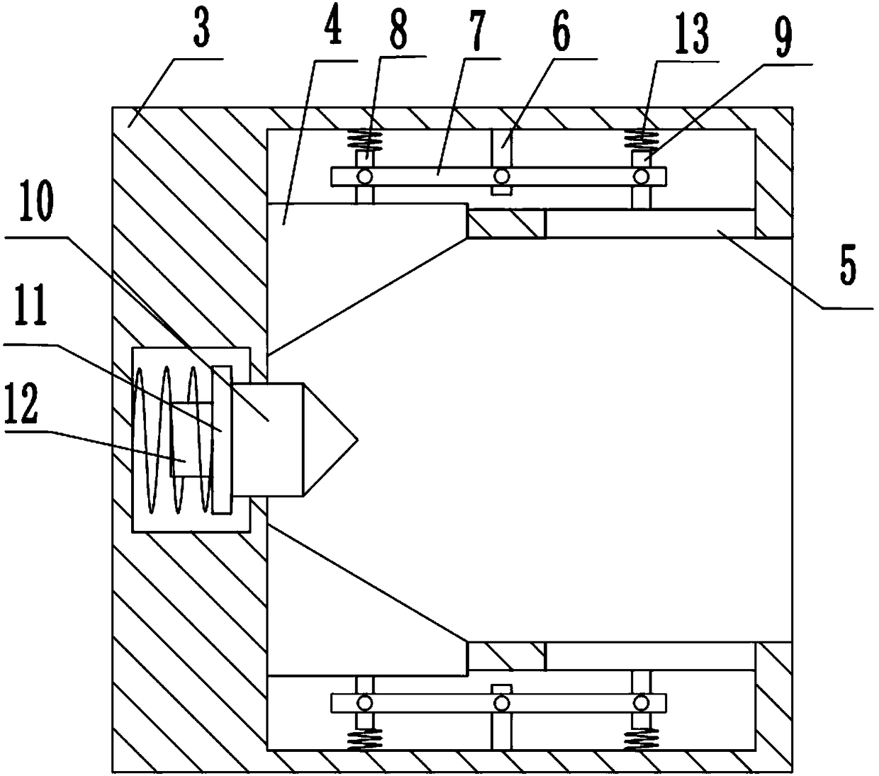
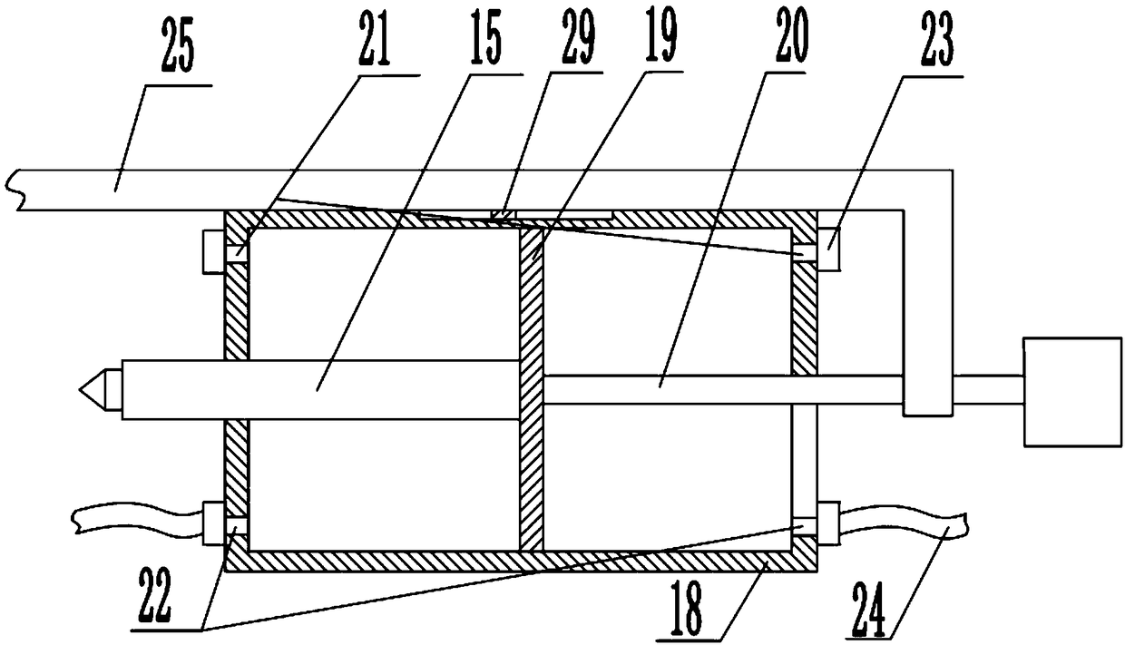
[0025] The reference signs in the drawings of the description include: machine tool spindle 1, machine tool guide rail 2, mounting seat 3, wedge block 4, clamping block 5, fixed rod 6, swing rod 7, first movable rod 8, second movable rod 9 , top 10, limit plate 11, positioning column 12, return spring 13, tailstock 14, pneumatic top 15, drive assembly 16, sliding sleeve 17, cylinder 18, piston plate 19, piston rod 20, air inlet 21, outlet Air port 22, one-way valve 23, air guide pipe 24, push rod 25, blade 26, rotating disk 27, fixed block 28, slide block 29, breach disc 30, rotating arm 31, cylindrical pin 32, sheave 33.

[0026] The embodiment is basically as attached figure 1 Shown: a cross-axis grinding and clamping device, including a machine tool spindle 1 and a machine tool guide rail 2, the machine tool spindle 1 is fixedly connected with a cross-axis clamping structure, suc...


PUM


Abstract

The invention relates to the field of automobile accessory manufacturing, in particular to a cross-shaped shaft grinding and clamping device. The cross-shaped shaft grinding and clamping device comprises a machine tool main shaft and a machine tool guide rail. The machine tool main shaft is fixedly connected with a cross-shaped shaft clamping structure. The cross-shaped shaft clamping structure comprises an installing base, a positioning assembly and clamping assemblies. The installing base is provided with an installing hole, grooves are formed in the side wall of the installing hole, and theclamping assemblies are arranged in the grooves. Each clamping assembly comprises a wedged block, a clamping block, a fixing rod, a swinging rod, a first movable rod and a second movable rod, whereinthe first movable rod and the second movable rod are provided with reset springs between the inner walls of the corresponding groove. A tail base is fixedly connected to the machine tool guide rail and comprises a pneumatic tip, a drive assembly and a sliding sleeve. The drive assembly is located on one side of the tail base and used for driving the pneumatic tip to horizontally move, and the tail base is further provided with a cross-shaped shaft rotation structure making the cross-shaped shaft rotate. The cross-shaped shaft grinding and clamping device can automatically clamp the cross-shaped shaft, and the cross-shaped shaft machining efficiency is improved.

Description

technical field [0001] The invention relates to the field of manufacturing and processing of auto parts, in particular to a cross-axis grinding and clamping device. Background technique [0002] The car differential is an important mechanical device for the car to turn, and the cross shaft is an important part in the car differential. Its quality level is related to whether the car differential can quickly, flexibly and reliably realize the car. Turning directly affects the performance of the car. [0003] The cross shaft is processed by machining, and the cross shaft needs to be ground after heat treatment, because heat treatment will produce certain deformation, and the surface may produce an oxide layer or a small amount of deformation. Grinding is placed after heat treatment, so the micro deformation caused by heat treatment can be eliminated after grinding, the precision of parts can be improved, and the oxide layer on the surface can also be removed to improve the qua...

Claims


Application Information

Patent Timeline
Patent Type & Authority Applications(China)
IPC IPC(8): B24B41/06B24B41/02B24B47/06B24B41/04B24B55/06
CPCB24B41/02B24B41/04B24B41/062B24B47/06B24B55/06
Inventor 项文增
Owner 宁波隆锐机械制造有限公司
Why Eureka
Try Eureka