
Plunger water pump integrated application system

A water pump and plunger technology, which is applied in the field of plunger water pump integrated application system, can solve the problems of increasing maintenance costs, reducing production efficiency, accelerating the failure of vulnerable parts of the pump body, etc., and achieves the effect of low operation and maintenance costs

Inactive Publication Date: 2019-02-12
WUHAN UNIV OF TECH
View PDF6 Cites 2 Cited by
  • Summary
  • Abstract
  • Description
  • Claims
  • Application Information

AI Technical Summary

Problems solved by technology

[0002] In high-lift applications, the efficiency of centrifugal pumps is low, and it is difficult to meet the qualified indicators of energy-saving operation. However, the high efficiency of plunger pumps is more and more popular with people, and there is even a tendency to completely replace centrifugal pumps.
However, compared with the advantages of large displacement and high speed operation of the centrifugal pump, the displacement of the plunger water pump is small and the operating speed is low, which cannot meet the water supply demand of large flow. If the displacement and speed are increased too much, it is necessary to increase the cylinder The diameter of the sleeve and the plunger increases the pulse movement of the plunger, which intensifies the vibration of the pump body, thereby accelerating the failure of the vulnerable parts of the pump body, reducing the service life of the plunger water pump, increasing maintenance costs, and reducing production efficiency.

Method used


Image

  • Plunger water pump integrated application system

Examples


Embodiment Construction

[0016] The present invention will be further described below in conjunction with accompanying drawing.

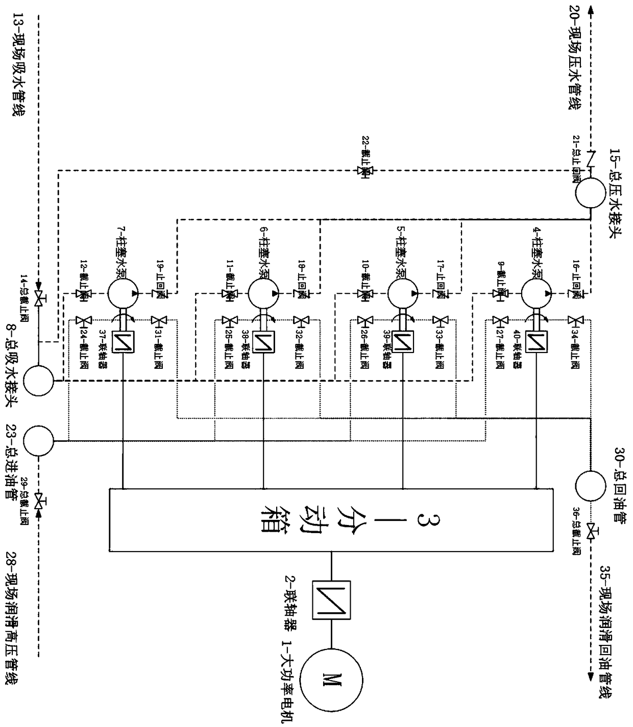
[0017] Such as figure 1 As shown, this embodiment provides a plunger water pump integrated operation system, including a motor 1, a coupling 2, a transfer case 3, several plunger water pumps, a water suction pipeline, a pressure water pipeline, and a lubricating oil system. This embodiment takes four plunger water pumps (4, 5, 6, 7) as an example for illustration. Each plunger water pump is fixed on one side of the transfer case through a hollow bracket. Connected with the input shaft of the transfer case 3, the power is transmitted to the four output shafts of the transfer case 3 through the intermediate transmission shaft of the transfer case 3, and the four output shafts of the transfer case pass through the couplings 37, 38, 39,40 link to each other with the input shaft of plunger pump 4,5,6,7. (can explain the power range of the motor)

[0018] The water suction pip...


PUM


Abstract

The invention discloses a plunger water pump integrated application system. The plunger water pump integrated application system is characterized by comprising a motor, a first coupler, a transfer case, a plurality of plunger water pumps, a water suction pipeline, a water pressing pipeline and a lubricating oil system, wherein the power of the motor is transmitted to an input shaft of the transfercase through the first coupler, the power is transmitted to a plurality of output shafts of the transfer case through an intermediate shaft, each plunger water pump is fixed on one side of the transfer case and is connected with the corresponding output shaft of the transfer case through a second coupler, the water suction pipeline is correspondingly connected with water suction openings of all the plunger water pumps, the water pressing pipeline is correspondingly connected with water pressing openings of all the plunger water pumps, and the lubricating oil system provides lubricating oil for each plunger water pump. According to the plunger water pump integrated application system, a perfect lubricating system and a concise water suction and water pressing pipeline system are adopted astechnical support, so that the high-pressure plunger pumps can run reliably for a long time, and the problems of low efficiency of a centrifugal pump under a high lift and small displacement of a single plunger water pump are well solved.

Description

technical field [0001] The invention relates to the technical field of plunger water pumps, in particular to an integrated operation system of plunger water pumps. Background technique [0002] In high-lift applications, the efficiency of centrifugal pumps is low, and it is difficult to meet the qualified indicators of energy-saving operation. However, the high efficiency of plunger pumps is more and more popular with people, and even has a tendency to completely replace centrifugal pumps. However, compared with the advantages of large displacement and high speed operation of the centrifugal pump, the displacement of the plunger water pump is small and the operating speed is low, which cannot meet the water supply demand of large flow. If the displacement and speed are increased too much, it is necessary to increase the cylinder The diameter of the sleeve and the plunger increases the pulse movement of the plunger, which intensifies the vibration of the pump body, thereby ac...

Claims


Application Information

Patent Timeline
IPC IPC(8): F04B17/03F04B53/16F04B53/18F04B49/03
CPCF04B17/03F04B49/03F04B53/16F04B53/18
Inventor 沈顺成赵明威黎章杰
Owner WUHAN UNIV OF TECH
Learn More