Low-density material perspective imaging method and system

A technology of low-density materials and imaging methods, which is applied in the field of low-density material perspective imaging methods and systems, and can solve problems such as multiple output, wire evaluation, and qualitative accuracy of product failure.

Active Publication Date: 2019-02-12
SHENZHEN STS MICROELECTRONICS
View PDF6 Cites 2 Cited by
  • Summary
  • Abstract
  • Description
  • Claims
  • Application Information

AI Technical Summary

Problems solved by technology

[0003] Therefore, the existing technology is difficult to carry out the necessary evaluation of the wires of this type of components under non-destructive conditions, and it is impossible to characterize defects such as missing, deformed, excess, and abnormal welding positions of the metal wires; it will lead to failure analysis. The evidence chain is incomplete, which affects the qualitative accuracy of product failure, thereby affecting the quality evaluation of components

Method used


Image

  • Low-density material perspective imaging method and system
  • Low-density material perspective imaging method and system
  • Low-density material perspective imaging method and system

Examples


Embodiment 1

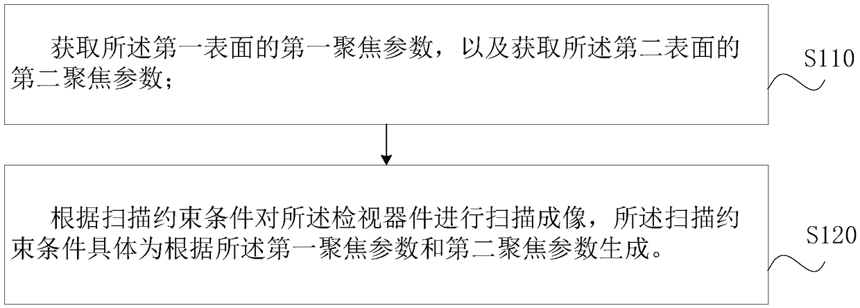
[0071] Such as image 3 It is a schematic flow chart of a low-density material perspective imaging method.

[0072] Exemplary, low-density material fluoroscopy imaging method can be used for such as Figure 4 , Figure 5 The inspection device 120 within the package body 110 of the illustrated component 100 is imaged.

[0073] The viewing device 120 includes a first element 121 having a first surface 101 , a second element 122 having a second surface 102 , and a wire 123 connecting the first surface 101 and the second surface 102 .

[0074] Such as Figure 4 and Figure 5 As shown, the first surface 101 and the second surface 102 are located on different planes. In practice, the wires 123 inside the component 100 , especially the two ends of the wires 123 are usually not on the same plane, and there is a certain height difference. Exemplary, such as Figure 4 and Figure 5 As shown, the first element 121 is the chip portion of the inspection device 120, the second eleme...

Embodiment 2

[0146] Such as Figure 16 The low-density material perspective imaging method shown is used for imaging the inspection device 120 inside the package body 110 of several components and devices 100 .

[0147] The low-density material perspective imaging method of this embodiment includes the following steps:

[0148] Step S210, arranging several components 100 in a preset manner.

[0149] Each component 100 must be free from surface defects and dirt. If there is serious dirt and highly absorbent trace contamination, such as pencil marks, etc., it needs to be cleaned.

[0150] Exemplarily, several components 100 of the same structure or type are arranged in a row, or arranged in a rectangular array, and a preset manner of arrangement can be established according to the scanning characteristics of the ultrasonic scanning device.

[0151] Step S220, scanning and imaging one of the several components 100 according to the low-density material perspective imaging method according to...


PUM

PropertyMeasurementUnit
densityaaaaaaaaaa
diameteraaaaaaaaaa
diameteraaaaaaaaaa

Abstract

The invention discloses a low-density material perspective imaging method and system, which is used for imaging an inspection device inside a packaging body through ultrasonic wave. The inspection device comprises a first element with a first surface, a second element with a second surface, and a wire connecting the first surface and the second surface; and the first surface and the second surfaceare located in different planes, and the density of the wire is less than 5 grams per cubic centimeter. The low-density material perspective imaging method includes the steps that a first focusing parameter of the first surface and a second focusing parameter of the second surface are obtained; according to the scanning constraint conditions, scanning imaging is carried out on the inspection device, and the scanning constraint conditions are specifically generated according to the first focusing parameter and the second focusing parameter. Not only can the good imaging effect on the first andsecond surfaces be obtained, but also the low-density wire can be well reflected in imaging results; and scanning imaging of elements with low-density wires under the non-destructive condition is realized.

Description

technical field [0001] The invention relates to the field of component detection, in particular to a low-density material perspective imaging method and system. Background technique [0002] Under the current laboratory conditions, the conventional X-RAY perspective imaging technology sometimes cannot image the wires in the components. For example, X-RAY perspective imaging cannot be used for the low-density metal wires in some components. Such as figure 1 and figure 2 They are the results of perspective imaging of the two components using X-RAY, and it can be seen that the wires in them are not reflected. [0003] Therefore, the existing technology is difficult to carry out the necessary evaluation of the wires of this type of components under non-destructive conditions, and it is impossible to characterize defects such as missing, deformed, excess, and abnormal welding positions of the metal wires; it will lead to failure analysis. The chain of evidence is incomplete, ...

Claims


Application Information

Patent Timeline
Patent Type & Authority Applications(China)
IPC IPC(8): G01N23/04
CPCG01N23/04
Inventor 刘金龙黄彩清吴凌
Owner SHENZHEN STS MICROELECTRONICS
Why Eureka
Try Eureka