Method for testing partial discharge of suspended particles in flowing transformer oil

A technology of transformer oil and partial discharge, which is applied in the direction of instruments, measuring electricity, measuring electrical variables, etc., to achieve the effect of easy promotion, speeding up the test process, and shortening time and cost

Inactive Publication Date: 2019-02-12
ELECTRIC POWER RESEARCH INSTITUTE OF STATE GRID SHANDONG ELECTRIC POWER COMPANY +2
View PDF6 Cites 5 Cited by
  • Summary
  • Abstract
  • Description
  • Claims
  • Application Information

AI Technical Summary

Problems solved by technology

However, according to the existing patent literature, there is no relatively complete test method to truly and

Method used


Image

  • Method for testing partial discharge of suspended particles in flowing transformer oil
  • Method for testing partial discharge of suspended particles in flowing transformer oil
  • Method for testing partial discharge of suspended particles in flowing transformer oil

Examples


Embodiment 1

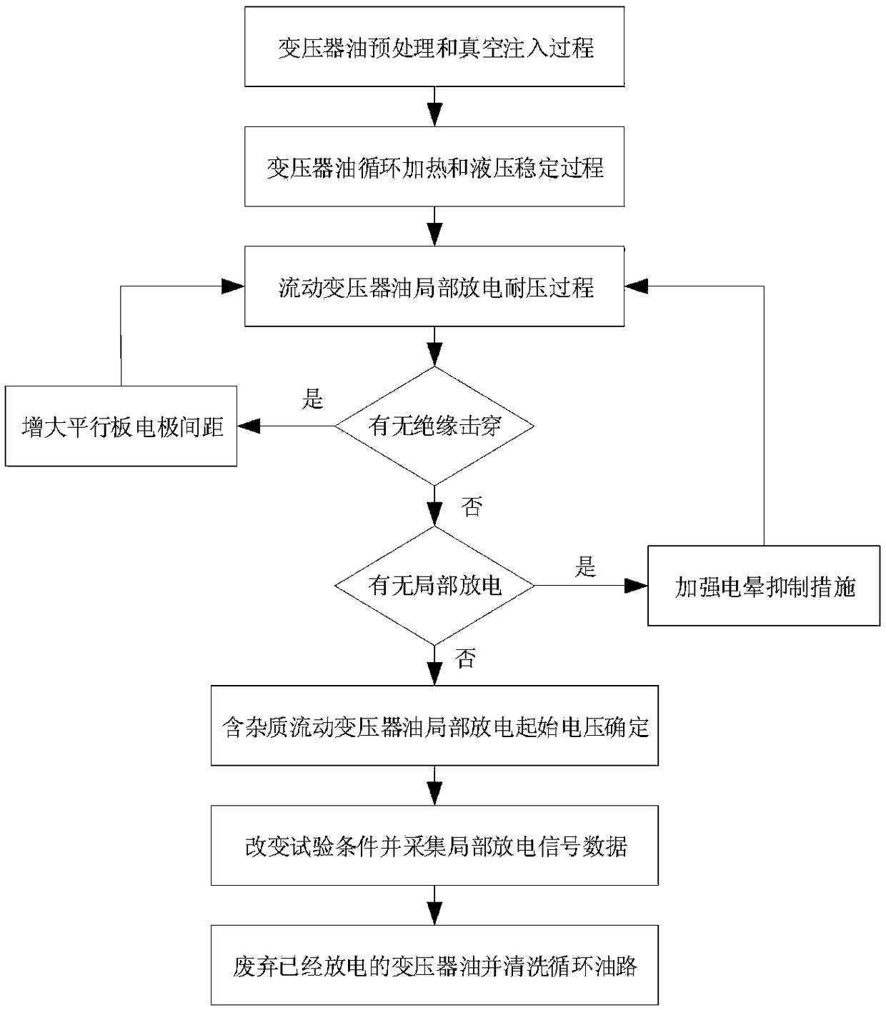
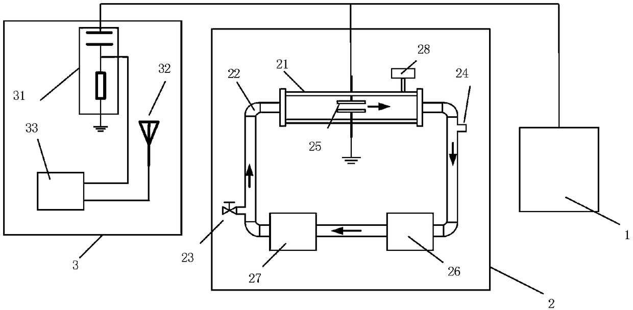
[0094] Based on attached figure 1 test method and attached figure 2 The simple mobile transformer oil suspended particle discharge generating device measures the partial discharge signal of the mobile transformer oil containing metal suspended particles within a single power frequency cycle at a flow rate of 0.06m / s.

[0095] First follow step 1);

[0096] In step 2), the temperature control component 27 heats the temperature of the transformer oil to 55° C., and the flow rate control component 26 accelerates the transformer oil to 0.06 m / s;

[0097] In step 3), no insulation breakdown occurs, and the measured maximum partial discharge amplitude is 4pC, and the partial discharge test can be carried out;

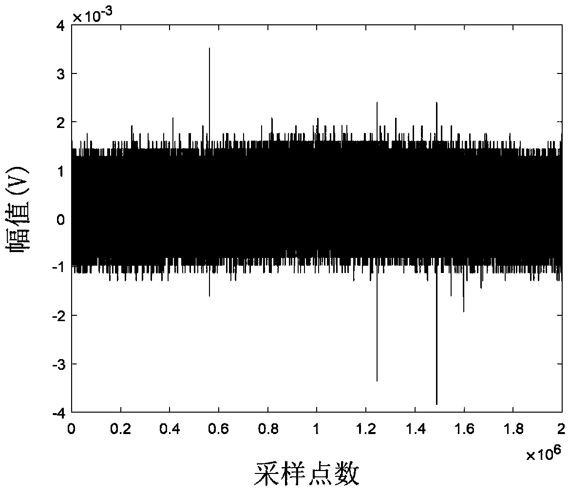
[0098] Inject spherical iron particles with a diameter of 150 μm through the suspended particle injection port 24, and the suspended particle concentration is 1.0 g / L. After waiting for 10 minutes, turn on the corona-free applied voltage pressurization device 1, and turn o...

Embodiment 2

[0101] After completing the partial discharge signal measurement of the moving transformer oil containing metal suspended particles in a single power frequency cycle in the case of a flow rate of 0.06m / s in Example 1, the transformer oil in the waste oil circulation device 2 is used Step 1) Clean the oil circulation device 2 several times with the transformer oil heated up and vacuum-dried, and repeat steps 1), 2), 4) and 5). Other conditions such as temperature and pressure remain unchanged, the difference lies in step 2) The flow rate control assembly 26 accelerates the transformer oil to 0.30 m / s. Inject spherical iron particles with a diameter of 150 μm through the suspended particle injection port 24, and the suspended particle concentration is 1.0 g / L. After waiting for 10 minutes, turn on the corona-free external voltage pressurization device 1, and turn on the partial discharge measurement device 3 to measure the local The discharge signal is gradually boosted to 18kV,...


PUM


Abstract

The invention provides a method for testing partial discharge of suspended particles in flowing transformer oil. The method comprises the following steps that 1) a transformer oil pretreatment and vacuum injection process is performed; step 2) a transformer oil circulation heating and hydraulic stabilizing process is performed; step 3) a partial discharge withstand voltage process of the flowing transformer oil is carried out; step 4) the initial voltage of partial discharge of the flowing transformer oil containing the suspension particles is determined; step 5) the test conditions are changed and the partial discharge signal data is acquired; and step 6) the discharged transformer oil is abandoned and the circulating oil path is cleaned. According to the method, various test conditions are considered, the test conditions are strictly controlled, and the actual environment conditions in the transformer are really simulated; and by adopting the test method, the test process can be accelerated, the time cost can be lowered, the partial discharge of the suspension particles can be really and reliably measured, and the method has relatively high practical engineering value.

Description

technical field [0001] The invention relates to the technical field of transformer insulation detection, in particular to a partial discharge test method for suspended particles in flowing transformer oil. Background technique [0002] As one of the core equipment of power transmission and transformation in modern power grid, large power transformer plays a vital role in its safe and reliable operation for the entire power grid. Large-scale power transformers usually use oil-paper composite insulation, and the insulation quality of transformer oil has a significant impact on the insulation performance of the transformer. However, during the process of manufacturing, transportation, on-site filling, operation and maintenance, transformer oil inevitably contains a certain amount of suspended particles. Under the action of a strong electric field, these particles can induce partial discharge, which may cause insulation breakdown accidents in severe cases, threatening the safet...

Claims


Application Information

Patent Timeline
IPC IPC(8): G01R31/12
CPCG01R31/1281
Inventor 周加斌辜超雍军朱庆东王建朱孟兆王学磊朱文兵唐炬肖淞骆欣瑜邢海文李龙龙韩明明许伟伊锋高志新顾朝亮
Owner ELECTRIC POWER RESEARCH INSTITUTE OF STATE GRID SHANDONG ELECTRIC POWER COMPANY
Why Eureka
Try Eureka