LED (Light Emitting Diode) lens design method for non-planar uniform illumination

A LED lens and uniform lighting technology, which is applied in lighting and heating equipment, parts of lighting devices, lighting devices, etc., can solve problems such as inability to uniform lighting, and achieve design time saving, high energy utilization, and easy processing and manufacturing Effect

Active Publication Date: 2019-02-12
FUDAN UNIV
View PDF6 Cites 3 Cited by
  • Summary
  • Abstract
  • Description
  • Claims
  • Application Information

AI Technical Summary

Problems solved by technology

[0004] The purpose of the present invention is to overcome the deficiency that the traditional free-form surface lens cannot perform uniform illumination on non-plane, and provide a design method of LED single free-form surface lens for non-planar illumination, aiming at obtaining high efficiency and high uniformity on non-planar objects. degree of illumination spot

Method used


Image

  • LED (Light Emitting Diode) lens design method for non-planar uniform illumination
  • LED (Light Emitting Diode) lens design method for non-planar uniform illumination
  • LED (Light Emitting Diode) lens design method for non-planar uniform illumination

Examples


Embodiment Construction

[0031] The present invention will be further described below in conjunction with the embodiments and drawings.

[0032] The LED lens design method for non-planar uniform illumination of the present invention specifically includes the following steps:

[0033] (1) Determine the light intensity distribution of the LED.

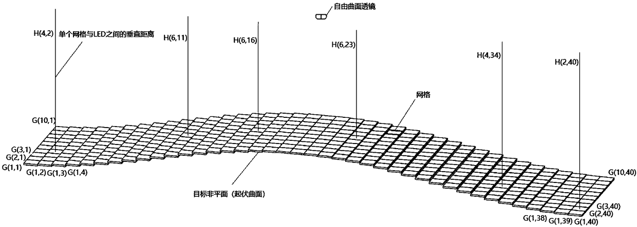
[0034] (2) In space rectangular coordinates, establish a free-form lens mathematical model based on the light intensity distribution of the LED, take the position of the LED as the origin of the coordinate, and place the target non-planar directly above the XOY plane, and the free-form lens is located between the LED and the target non-planar Between, the Z coordinate of each component should be greater than zero, the specific method is as follows:

[0035] Set the refractive index of the free-form surface material to n A , The LED is located at the origin of the Cartesian coordinate system, under normal temperature conditions, the refractive index of air is set to n B ...


PUM


Abstract

The invention belongs to the technical field of optical lenses, and particularly relates to an LED lens design method for non-planar uniform illumination. The method comprises the following steps of:dividing a target non-planar into a plurality of grids on a projection surface of a XOY plane, introducing into a matrix, indicating a vertical distance between each grid and the LED; substituting thevertical distance into a traditional lens mathematical model, iteratively solving the model by setting the expected irradiance distribution of the target non-planar, and obtaining multiple sets of discrete points; and using a three-dimensional drawing to get a final free-form surface lens. The optical device is a single free-form surface lens, is easy to process, and has good light distribution performance. The lens performs secondary light distribution on the emitted light of the LED, and obtains a uniform irradiated light spot on the target non-plane, thereby overcoming the insufficiency that the conventional free-form lens cannot perform uniform illumination on the non-planar. According to the LED lens design method for the non-planar uniform illumination, the irradiation uniformity isgood, the uniformity on the target non-planar can reach 70.01%, and the utilization rate of the LED energy can reach 83.51% or more.

Description

Technical field [0001] The invention belongs to the technical field of optical lenses, and in particular relates to an LED lens design method for non-planar uniform illumination. Background technique [0002] As a new-generation light source, LED has the advantages of energy saving, high efficiency, and long life. However, most LEDs are used as Lambertian light sources and have poor lighting effects and need to be light-distributed. In recent years, LED light distribution technology has developed rapidly. Researchers have studied and proposed various design methods to achieve an ideal irradiance distribution on the target lighting surface. Previous researches mainly focused on structural design, solving methods, and obtaining special irradiance distribution. Secondary optical design has also been proven to be an effective method to solve the above problems. [0003] In order to improve the energy utilization and irradiation uniformity of the LED lighting system, the early research...

Claims


Application Information

Patent Timeline
Patent Type & Authority Applications(China)
IPC IPC(8): G02B27/00F21V5/04F21Y115/10
CPCF21V5/04F21Y2115/10G02B27/0012
Inventor 孔令豹孙翔徐敏
Owner FUDAN UNIV
Why Eureka
Try Eureka