Handheld dust collector

A vacuum cleaner and handheld technology, which is applied in the field of household appliances, can solve the problems of uneven distribution and insufficient lightness of operation, and achieve the effect of reasonable layout, compact structure and uniform weight distribution

Pending Publication Date: 2019-02-15
NINGBO ZHEKAI ELECTRIC CO LTD
View PDF1 Cites 5 Cited by
  • Summary
  • Abstract
  • Description
  • Claims
  • Application Information

AI Technical Summary

Problems solved by technology

[0003] After investigation, the existing Chinese patent No. CN201810459076 "A Handheld Vacuum Cleaner" includes a handle; The air inlet hole on the side wall of the dust separator communicates with one end of the connecting pipe, and the other end of the connecting pipe is used to communicate with the suction pipe; the dust separator is used for dust separation; the vacuum generator communicates with the dust separator , used to generate negative pressure, the airflow containing dust is sucked from the air inlet hole, and after the dust is separated by the dust separator, the clean airflow is sucked away by the vacuum generator. The dust separator, vacuum generator and The battery components are all arranged on the upper part of the handle, which is compact in structure and small in size, but because its weight is concentrated on the upper part of the handle, the distribution is uneven, it is not light enough to operate, and the battery needs to be replaced after a long period of use, so the structural layout needs to be further improved. Improve

Method used


Image

  • Handheld dust collector
  • Handheld dust collector
  • Handheld dust collector

Examples


Embodiment 1

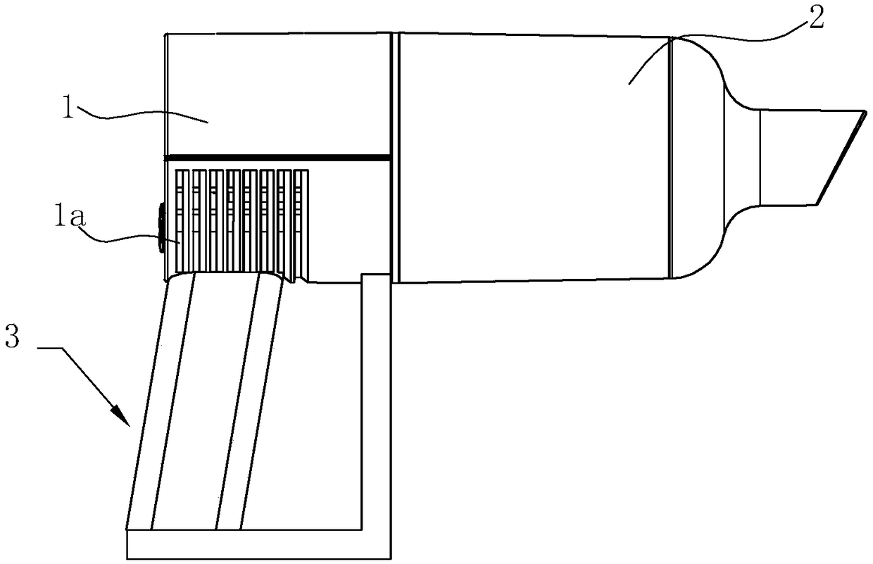
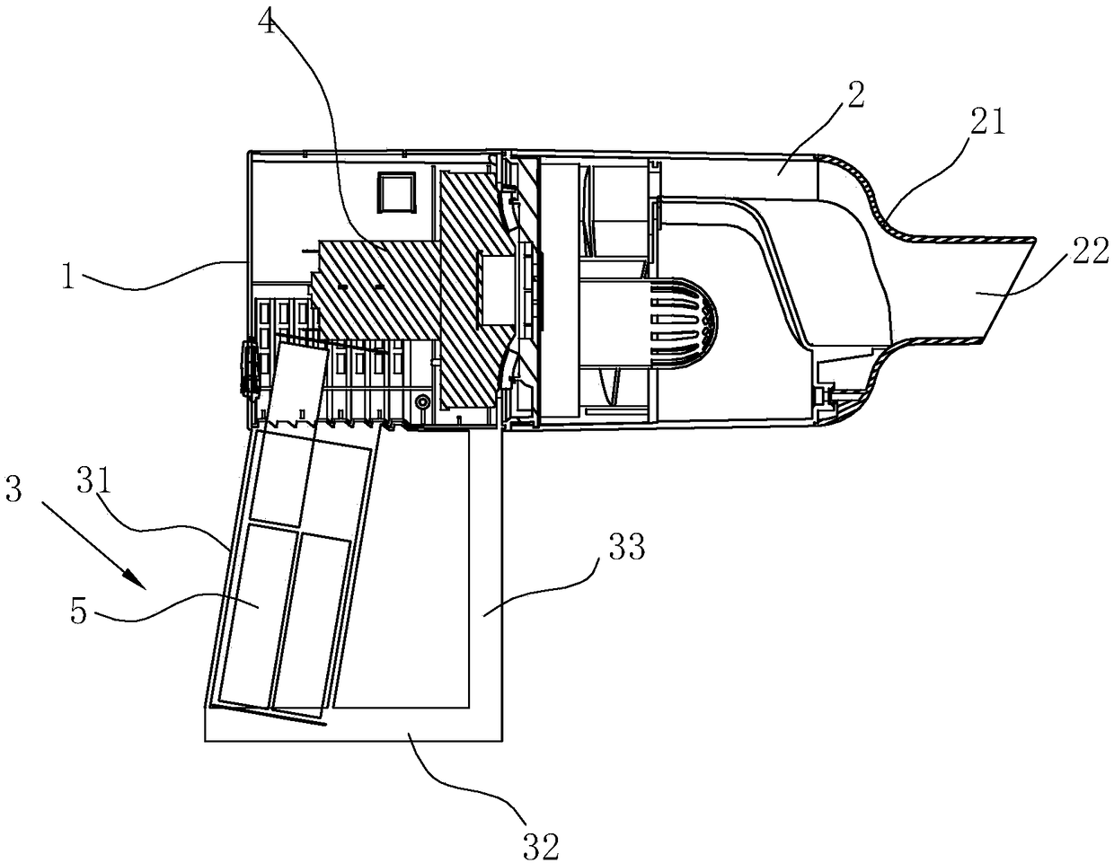
[0025] Such as Figure 1-7 As shown, a hand-held vacuum cleaner includes a vacuum cleaner main body 1 with a vacuum generator 4 built in, a dust collection cup 2 and a battery pack 5. The vacuum cleaner main body 1 is formed by combining a left housing 11 and a right housing 12. After the housing 11 and the right housing 12 are combined, a cylindrical cavity for the vacuum generator 4 is formed on the upper part, and a handle part 3 is formed on the lower part. The dust collecting cup 2 is a circle corresponding to the upper part of the vacuum cleaner main body 1. The dust collection cup 2 is detachably sealed and arranged on the front side of the vacuum cleaner main body 1, and communicates with each other. This detachable connection can adopt the traditional snap-fit ​​connection, etc. The vacuum in the dust collection cup 2 and the vacuum cleaner main body 1 The generator 4 is coaxially arranged front and rear. The cylindrical structure of the vacuum cleaner main body 1 is ...

Embodiment 2

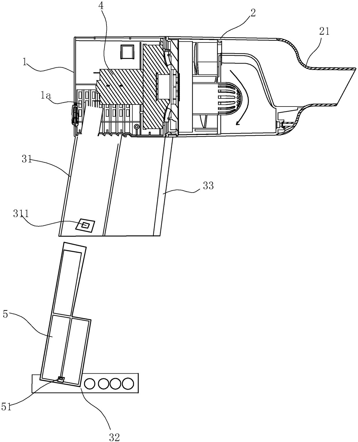
[0030] Such as Image 6 As shown, the difference from Embodiment 1 is that the battery pack 5 of this embodiment is detachably arranged in the support frame 33, the support frame 33 is a hollow structure with an open lower end, and the lower end of the battery pack 5 is arranged on the base 32, It is detachably inserted in the support frame 33, and a buckle groove 331 is provided on the outer side of the lower end of the support frame 33, and a corresponding buckle 51 is provided on the outer side of the lower end of the battery pack 5, and the battery pack 5 is inserted in the support frame 33 through the clip. The cooperation between the buckle 51 and the buckle groove 331 is detachably connected with the support frame 33 .

Embodiment 3

[0032] Such as Figure 7As shown, the difference from Embodiment 1 is that the handle part 3 of this embodiment is a U-shaped integrated structure composed of a base 32, a handle 31 and a support frame 33, wherein the handle 31 is arranged on the circle of the vacuum cleaner body 1 inclined backwards. At the lower part of the rear end of the cylinder structure, the support frame 33 is arranged at the lower front end of the cylinder structure of the vacuum cleaner main body 1, and the handle 31 is provided with a cavity for inserting the battery pack 5, and the battery pack 5 passes through the left housing 11 and the right housing. The 12 pairs are fixedly arranged in the cavity of the handle 31, and batteries 53 are arranged in the battery pack 5 and the base 32, so that the capacity of the battery 53 can be made very large, and the space is fully utilized. There is a charging socket, and the battery pack 5 can be charged.

[0033] In this embodiment, the battery pack 5 is a...


PUM


Abstract

A handheld dust collector comprises a dust collector body with a built-in vacuum generator, a dust collecting cup and a battery pack. An air outlet is formed in the dust collector body. The dust collector is characterized in that the dust collecting cup is detachably arranged at the front end of the dust collector body, the dust collecting cup and the vacuum generator are coaxially and transversely arranged front and back, and a handle part is downwards formed at the rear end of the dust collector body; the battery pack is fixedly arranged in the handle part or the battery pack is detachably inserted into the handle part; the handle part and the battery pack are connected and fixed through buckling. The dust collector is more compact in structural design, more reasonable in layout, less inair volume loss and large in wind power, the operation is convenient, labor is saved, and the dust collector is convenient to store and the carry and very convenient to use.

Description

technical field [0001] The invention belongs to the technical field of household appliances and relates to a vacuum cleaner, in particular to a hand-held vacuum cleaner. Background technique [0002] The vacuum cleaner is a commonly used vacuuming tool in the home. Its working principle is to use the motor to drive the blades to rotate at high speed, generate negative air pressure in the sealed housing, and absorb dust. Vacuum cleaners can be divided into vertical, horizontal and hand-held according to their structure. Among them, hand-held vacuum cleaners are widely used because of their small size, light weight, and convenient use and storage. [0003] After investigation, the existing Chinese patent No. CN201810459076 "A Handheld Vacuum Cleaner" includes a handle; The air inlet hole on the side wall of the dust separator communicates with one end of the connecting pipe, and the other end of the connecting pipe is used to communicate with the suction pipe; the dust separ...

Claims


Application Information

Patent Timeline
Patent Type & Authority Applications(China)
IPC IPC(8): A47L5/24A47L9/10A47L9/32A47L9/00A47L9/28
CPCA47L5/24A47L9/00A47L9/106A47L9/2884A47L9/322
Inventor 胡海荣顾利锁
Owner NINGBO ZHEKAI ELECTRIC CO LTD
Why Eureka
Try Eureka