Drainage pipe

A drainage tube and tube body technology, applied in the field of drainage tubes, can solve problems such as cumbersome operation and blockage, and achieve the effects of reducing manual operation, maintaining smoothness and improving use efficiency.

Pending Publication Date: 2019-02-15
SECOND AFFILIATED HOSPITAL SECOND MILITARY MEDICAL UNIV
View PDF0 Cites 0 Cited by
  • Summary
  • Abstract
  • Description
  • Claims
  • Application Information

AI Technical Summary

Problems solved by technology

However, when this hollow tube encounters larger formed blood clots, food or feces residues, and tissue debris, it often becomes blocked, and usually requires manual extrusion to crush the blockage, so that the drainage tube is unobstructed. The operation is cumbersome and requires constant attention

Method used


Image

  • Drainage pipe
  • Drainage pipe
  • Drainage pipe

Examples


Embodiment 1

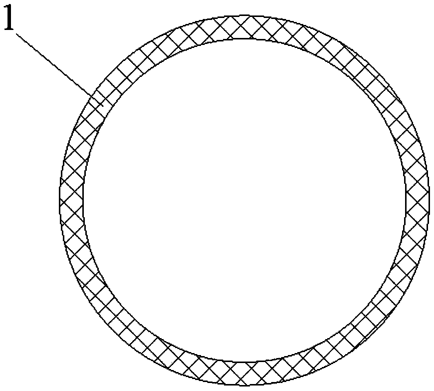
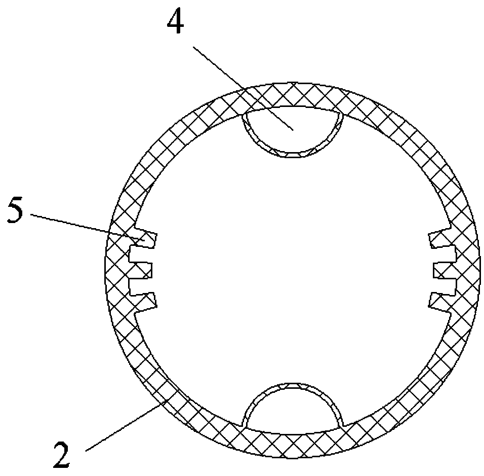
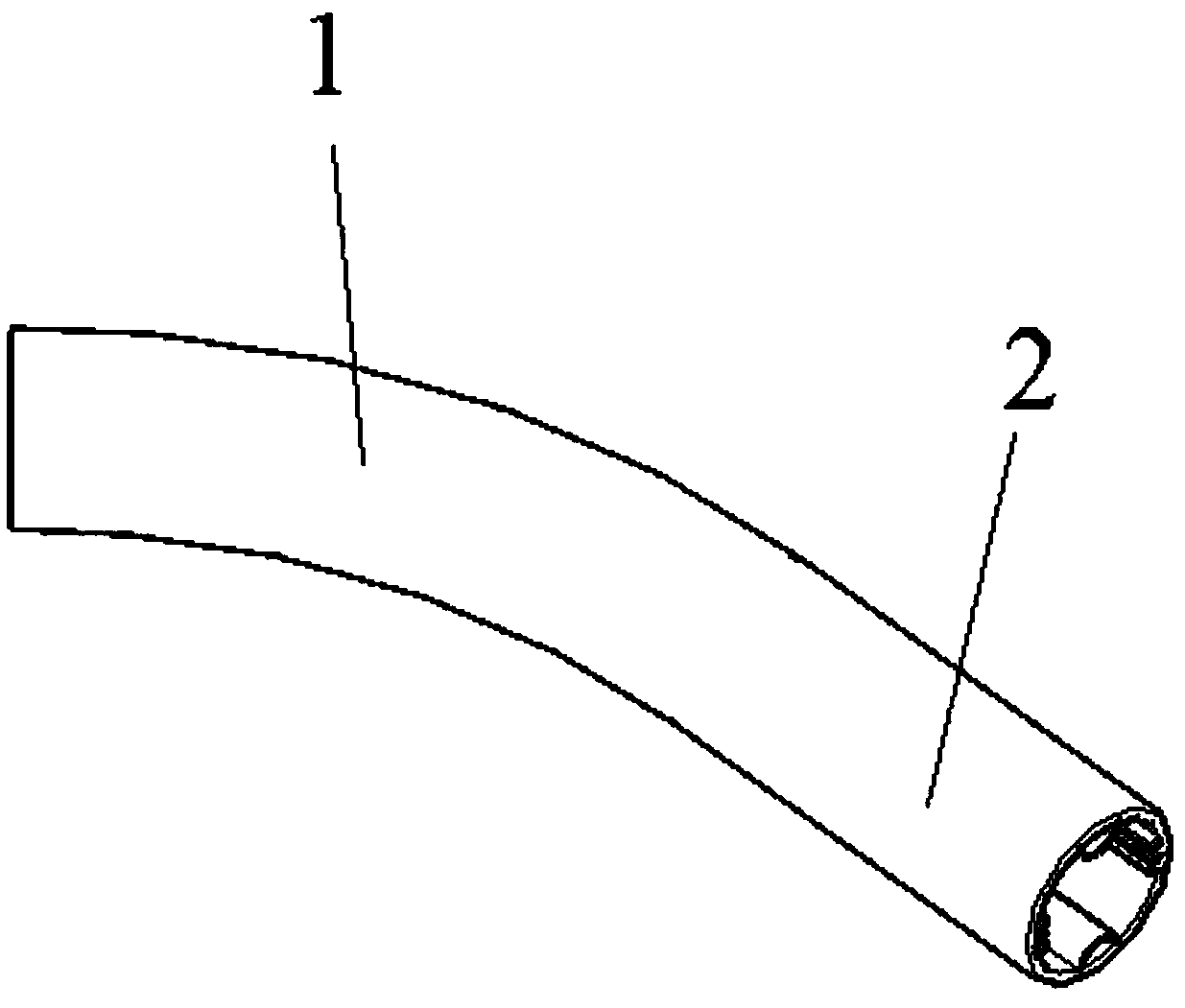
[0052] An exemplary embodiment of the present invention, such as Figure 1~3 As shown, a drainage tube includes a first tube body 1 and a second tube body 2, the second end of the first tube body 1 is connected to the first end of the second tube body 2, the first tube body 1 and the second tube body The pipe body 2 is integrally formed.

[0053] The first tube body 1 is a hollow tube made of transparent silica gel.

[0054] The inner diameter of the first pipe body 1 is equal to the inner diameter of the second pipe body 2 , and the outer diameter of the first pipe body 1 is equal to the outer diameter of the second pipe body 2 .

[0055] The length of the first pipe body 1 is greater than or equal to the length of the second pipe body 2 .

[0056] In this embodiment, preferably, the length of the first pipe body 1 is greater than the length of the second pipe body 2 , and the ratio of the length of the first pipe body 1 to the length of the second pipe body 2 is greater th...

Embodiment 2

[0072] This embodiment is a preferred embodiment of the present invention. The difference between this embodiment and Embodiment 1 lies in that the second pipe body 2 has a different structure and includes a third pipe body 3 .

[0073] A drainage tube in this embodiment includes a first tube body 1, a second tube body 2 and a third tube body 3, the second end of the first tube body 1 is connected to the first end of the second tube body 2, the second tube body 2 The first end of the three pipe bodies 3 is connected to the second end of the second pipe body 2 , and the first pipe body 1 , the second pipe body 2 and the third pipe body 3 are integrally formed.

[0074] Wherein, the structure of the first pipe body 1 is the same as that of Embodiment 1, and will not be repeated here.

[0075] The inner diameter of the first pipe body 1, the inner diameter of the second pipe body 2 and the inner diameter of the third pipe body 3 are equal, the outer diameter of the first pipe bod...

Embodiment 3

[0100] This embodiment is a preferred embodiment of the present invention, and the difference between this embodiment and Embodiment 2 lies in that the structures of the second pipe body 2 and the third pipe body 3 are different.

[0101] A drainage tube in this embodiment includes a first tube body 1, a second tube body 2 and a third tube body 3, the second end of the first tube body 1 is connected to the first end of the second tube body 2, the second tube body 2 The second end of the second pipe body 2 is connected to the first end of the third pipe body 3 , and the first pipe body 1 , the second pipe body 2 and the third pipe body 3 are integrally formed.

[0102] Further, in this embodiment, the ratio of the length of the first pipe body 1 to the length of the second pipe body 2 is 10:1, and the ratio of the length of the second pipe body 2 to the length of the third pipe body 3 is 2 :1.

[0103] Wherein, the structure of the first pipe body 1 is the same as that of Embo...


PUM


Abstract

The invention relates to a drainage pipe. The drainage pipe comprises a first pipe body and a second pipe body, wherein the first pipe body is hollow; a first end of the second pipe body is connectedwith a second end of the first pipe body, and the first pipe body and the second pipe body are integrally formed; the second pipe body comprises a plurality of side-wall pipes and a plurality of firstpressure-proof structures; the side-wall pipes are symmetrically arranged on the inner wall of the second pipe body in a circle, and a few of first pressure-proof structures are arranged between every two adjacent side-wall pipes. The drainage pipe has the advantages that the drainage pipe is designed into two sections, the drainage pipe is provided with the two pipe bodies with the sections in different shapes, the first pipe body is hollow, and the second pipe body is hollow and is provided with the side-wall pipes, so that large-sized blood clots are easily discharged, the problem that a traditional drainage pipe is blocked by the large-sized blood clots, and the drainage pipe needs to be manually squeezed to discharge the blood clots is avoided, and the using efficiency of the drainage pipe is improved; due to the arrangement of the pressure-proof structures, the problem can be avoided that the drainage pipe is deformed due to squeezing.

Description

technical field [0001] The invention relates to the technical field of medical instruments, in particular to a drainage tube. Background technique [0002] Drainage tube is a commonly used postoperative device, which is mainly used to guide pus, blood or other fluids accumulated in human tissues or body cavities to the outside of the body to prevent postoperative infection and promote wound healing. [0003] Existing drainage tubes are usually one-stage hollow pipes or two-stage hollow pipes. [0004] One-piece hollow tube, as the name suggests, is a hollow tube without a special shape. This kind of hollow tube has problems such as low drainage efficiency and easy extrusion deformation. [0005] Two-stage hollow tube, including a hollow tube and a hollow tube with a special shape, the radial section of the hollow tube with a special shape is usually a cross section, that is, the interior of the hollow tube is divided into four chambers room. However, when this hollow tube...

Claims


Application Information

Patent Timeline
IPC IPC(8): A61M25/14
CPCA61M25/0023A61M25/0043
Inventor 肖建如万维刘铁龙许克寒楼棪杨建黄权李林万昌丽魏海峰杨兴海
Owner SECOND AFFILIATED HOSPITAL SECOND MILITARY MEDICAL UNIV
Why Eureka
Try Eureka