Prefabricated assembling cast-in-place joint ring beam mold

A prefabricated assembly and cast-in-place technology, which is applied in molds, manufacturing tools, mold fixtures, etc., can solve problems such as difficulty in ensuring the quality of ring beams, unsatisfactory effects, and reduced construction efficiency, so as to shorten the construction period and ensure construction quality , The effect of reducing cumbersome processes

Inactive Publication Date: 2019-02-15
CHINA THIRD METALLURGICAL GRP
View PDF0 Cites 8 Cited by
  • Summary
  • Abstract
  • Description
  • Claims
  • Application Information

AI Technical Summary

Problems solved by technology

At present, the main construction methods of masonry ring beams on construction sites are mostly on-site manual pouring, and the ring beam molds are mostly made temporarily on site. Not only is the construction difficult, but the quality of the ring beams is difficult to guarantee. The strength of the concrete can only be carried out after demoulding, which reduces the construction efficiency

Method used


Image

  • Prefabricated assembling cast-in-place joint ring beam mold
  • Prefabricated assembling cast-in-place joint ring beam mold
  • Prefabricated assembling cast-in-place joint ring beam mold

Examples


Embodiment Construction

[0018] The specific embodiment of the present invention is described further below:

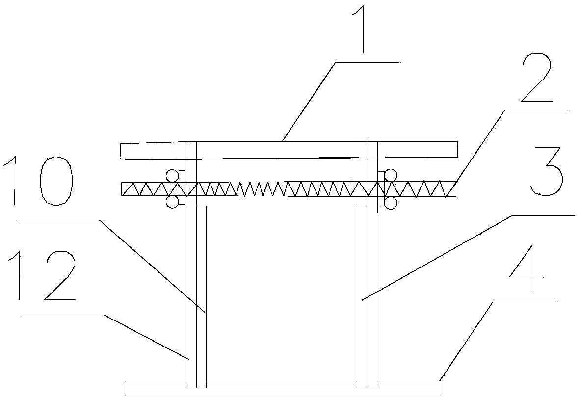
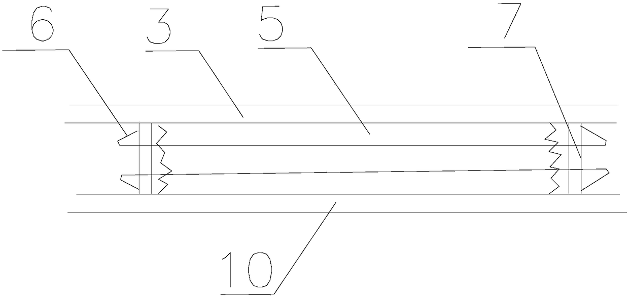
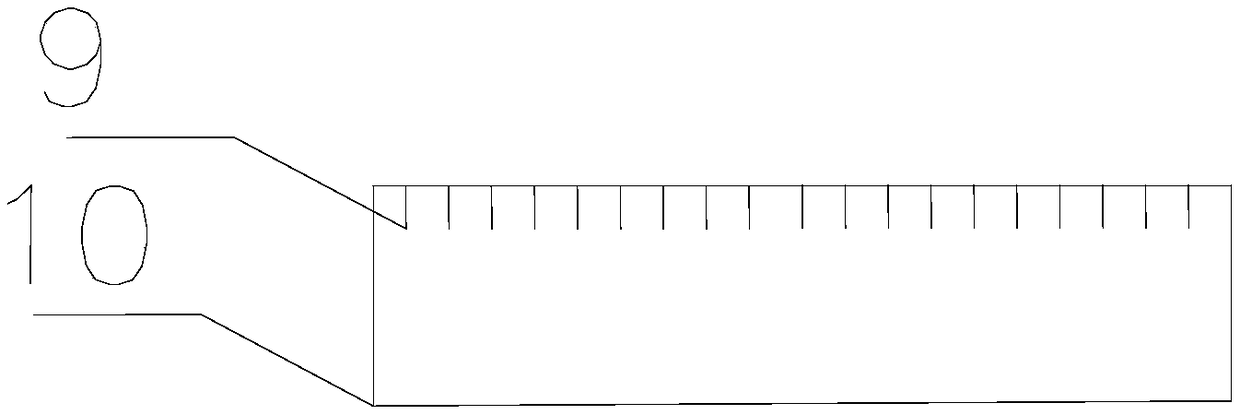
[0019] See Figure 1-Figure 3 , a prefabricated and assembled cast-in-place joint ring beam mold, including side formwork A10, side formwork B3, slide rail 1, lead screw 2, bottom formwork 4, inner formwork 7, wooden square 12, on the bottom formwork 4 there is Two vertical formwork grooves 11 arranged in parallel, the bottoms of side formwork A10 and side formwork B3 are respectively inserted in the formwork grooves 11 on the bottom template 4, and the wooden square 12 is arranged on the sides of side formwork A10 and side formwork B3. On the outside, slide rails 1 are placed on the upper ends of the two wooden cubes 12 oppositely arranged in the transverse direction. The screw 2 passes through the upper parts of the two wooden cubes 12 and is locked and positioned by nuts. The inner template 7 is arranged on the side template A10 and the side template A10. On the inner side of formwork B3 ...


PUM


Abstract

The invention discloses a prefabricated assembling cast-in-place joint ring beam mold. The prefabricated assembling cast-in-place joint ring beam mold comprises a side mold plate A, a side mold plateB, a sliding rail, a lead screw, a bottom mold plate, inner mold plates and wood beams; the bottom of the side mold plate A and the bottom of the side mold plate B are inserted into vertical mold grooves formed in the bottom mold plate; the wood beams are arranged on the outer side of the side mold plate A and the outer side of the side mold plate B; the sliding rail is arranged at the upper endsof the two wood beams which are transversely and oppositely arranged; the lead screw penetrates through the upper portions of the two wood beams and is locked and positioned through nuts; the inner mold plates are arranged on the inner sides of the side mold plate A and the side mold plate B and arranged at the two ends of a prefabricated component; and steel bar penetrating holes are formed in the inner mold plates, steel bars in the prefabricated component penetrate through the inner mold plates, the inner mold plates are positioned by hooks arranged at the two ends of the steel bars, and the inner mold plates are provided with grooves and protrusions. According to the prefabricated assembling cast-in-place joint ring beam mold, prefabricating of building ring beams with any size can beachieved, the construction quality can be guaranteed, the complex process can be effectively reduced, and the construction period can be shortened; and the prefabricated component can be combined witha cast-in-place structure in the construction site more easily, and the construction quality is guaranteed.

Description

technical field [0001] The invention relates to the field of engineering construction, in particular to a prefabricated and assembled cast-in-place joint ring beam mold. Background technique [0002] In the technical field of building construction, masonry is one of the main processes of building construction. At present, the main construction methods of masonry ring beams on construction sites are mostly on-site manual pouring, and the ring beam molds are mostly made temporarily on site. Not only is the construction difficult, but the quality of the ring beams is difficult to guarantee. The strength of the concrete can only be carried out after demoulding, which reduces the construction efficiency. Contents of the invention [0003] In order to overcome the defects of the existing technology, the object of the present invention is to provide a prefabricated assembled cast-in-place joint ring beam mold, which can realize the prefabrication of any size masonry ring beam, c...

Claims


Application Information

Patent Timeline
Patent Type & Authority Applications(China)
IPC IPC(8): B28B7/00B28B23/02
CPCB28B7/0029B28B7/0002B28B7/0014B28B23/024
Inventor 曹剑赵淼刘婷婷
Owner CHINA THIRD METALLURGICAL GRP
Why Eureka
Try Eureka