Full-automatic building hydraulic lifting device based on microcomputer

A technology of microcomputer and lifting device, which is applied in the direction of lifting device, lifting frame, etc., can solve the problems of high risk, low efficiency of manual operation, inconvenient handling, etc., and achieve the effect of low cost, reducing accidents, and convenient handling

Inactive Publication Date: 2019-02-15
江苏中友讯华信息科技有限公司
View PDF1 Cites 0 Cited by
  • Summary
  • Abstract
  • Description
  • Claims
  • Application Information

AI Technical Summary

Problems solved by technology

The hoist described in the above-mentioned patent relies on manual operation, which is very dangerous. At the same time, it is inefficient to rely on manual operation and is inconvenient to carry.

Method used


Image

  • Full-automatic building hydraulic lifting device based on microcomputer
  • Full-automatic building hydraulic lifting device based on microcomputer

Examples


Embodiment Construction

[0016] The present invention will be further described below in conjunction with accompanying drawing:

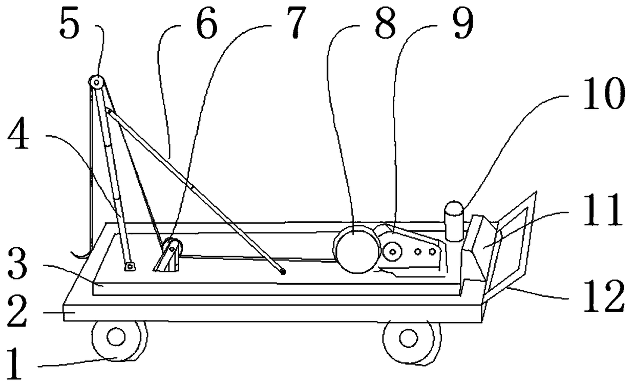
[0017] Such as figure 1 and 2 As shown, a fully automatic hydraulic lifting device for construction based on a microcomputer includes a rubber wheel 1, a base 2, a circuit box 3 and a telescopic support rod 4, the base 2 is composed of multi-layer steel plates welded, and the base 2 is equipped with Rubber wheel 1, rubber wheel 1 is used for mobile hoisting machine, and line box 3 is installed on the base 2, and line box 3 is used for placing each control line, and telescopic support bar 4 is installed on the line box 3, and support bar 4 is used for supporting weight. An upper pulley 5 is installed on the telescopic support rod 4, and the upper pulley 5 is used to change the direction of the wire rope. A pull rod 6 is installed on the line box 3, and the pull rod 6 is used to support the telescopic support rod 4. A lower pulley 7 is installed on the lower side of the pull...


PUM


Abstract

The invention discloses a full-automatic building hydraulic lifting device based on a microcomputer. The device comprises a rubber wheel, a base, a circuit box and an extension support rod; the rubberwheel is mounted under the base; the circuit box is mounted on the base; the extension support rod is mounted on the circuit box; an upper pulley is mounted on the extension support rod; a pull rod is mounted on the circuit box; a lower pulley is mounted on the circuit box; a rolling line wheel is mounted on the circuit box; a speed reducing motor is mounted on the circuit box; and a signal transreceiver is mounted on the circuit box. The device has the beneficial effects of small size, low cost and wide application range; meanwhile, APP control software is downloaded through a mobile phone,so that workers have no need to operate beside the machine, and accidents are reduced; and meanwhile, according to the hanging design, the device can be directly hung on an another power vehicle to pull away, so that the carrying is convenient.

Description

technical field [0001] The invention relates to the field of mechanical equipment, in particular to a microcomputer-based fully automatic hydraulic lifting device for construction. Background technique [0002] Cranes are used to lift low objects to higher ones, saving manpower and improving efficiency. The application number is: Chinese patent of 201010542295, the specific content is: provide a kind of hand hoist, comprise No. 1 fixed pulley located at the top and No. 2 fixed pulley located obliquely below, a stay rope is set on the No. 1 fixed pulley, One end of the stay rope is connected to the heavy object to be lifted, and the other end of the stay rope is wound on the No. 2 fixed pulley; a rotating handle is installed on the No. 2 fixed pulley, and a A snap ring that fixes the relative position. The hoist described in the above-mentioned patent relies on manual operation, which is dangerous, and at the same time, it is inefficient and inconvenient to carry. Therefor...

Claims


Application Information

Patent Timeline
Patent Type & Authority Applications(China)
IPC IPC(8): B66F7/02B66F7/06B66F7/28
CPCB66F7/02B66F7/0625B66F7/28
Inventor 梁继建
Owner 江苏中友讯华信息科技有限公司
Why Eureka
Try Eureka