A kind of mold canvas for pressing herringbone pattern on the surface of conveyor belt and its application

A technology of herringbone pattern and conveyor belt, which is applied in textile, textile, papermaking, fabric and other directions, can solve the problems of easy cracking and falling of horizontal bars, affecting the performance of conveyor belt grooves, complicated processing technology of conveyor belt, etc., so as to increase frictional force. Effect

Active Publication Date: 2021-03-02
无锡宝强工业织造有限公司
View PDF5 Cites 0 Cited by
  • Summary
  • Abstract
  • Description
  • Claims
  • Application Information

AI Technical Summary

Problems solved by technology

However, the processing technology of the conveyor belt is complicated. When the height of the transverse rib is too high, the transverse rib is easy to crack and fall under the action of bending stress when the conveyor belt passes through the roller, and at the same time affects the grooving performance of the conveyor belt.

Method used


Image

  • A kind of mold canvas for pressing herringbone pattern on the surface of conveyor belt and its application
  • A kind of mold canvas for pressing herringbone pattern on the surface of conveyor belt and its application

Examples


Embodiment 1

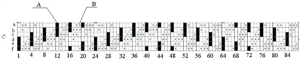
[0032] Such as figure 1 As shown, a mold canvas for pressing the herringbone pattern on the surface of the conveyor belt, the canvas is composed of several cyclic unit structures to form a positive and negative herringbone twill structure, and each unit structure includes several groups of warp and weft structures , formed by interweaving warp yarns and weft yarns; the warp yarns include first warp yarns A and second warp yarns B, and the weft yarns include a structure of weft yarns C; the warp yarns include 88 groups, and the weft yarns include 6 groups.

[0033] The warp yarns are numbered sequentially from left to right, named warp yarn 1 to warp yarn 88, wherein warp yarn 1, warp yarn 5, warp yarn 9, warp yarn 13, warp yarn 17, warp yarn 21, warp yarn 25, warp yarn 29, warp yarn 33, warp yarn 37. Warp yarn 41, warp yarn 45, warp yarn 49, warp yarn 53, warp yarn 57, warp yarn 61, warp yarn 65, warp yarn 69, warp yarn 73, warp yarn 77, warp yarn 81 and warp yarn 88 are the f...

Embodiment 2

[0042] Example 2 A mold canvas with a width of 1000 mm was produced.

[0043] Twisting process:

[0044] The primary twister is the R814 twister from Yichang Textile Machinery, and the double twister is the KV301 heavy-duty twister from Changzhou Kaizhou.

[0045] The warp yarns are of 2 different structures:

[0046] Warp yarn A, as the main warp yarn forming the positive and negative concave-convex effects: first, the single-strand 940dtex nylon 66 industrial yarn is twisted into 180 twists / m, and the twist direction is the primary twisted line of S, and then the above-mentioned 12 strands of nylon 66 industrial yarn, After ply twisting with 120 twists / m, twisting in Z direction, and then plying and double-twisting the above-mentioned 3 twisted yarns, twisting degree 120 twists / m, twisting in S direction, plying into: 940dtex X 12 X 3 twine.

[0047] Warp yarn B, as the matrix for forming the mold canvas, adopts nylon 66 industrial yarn, single-strand 940dtex nylon 66 ind...


PUM

PropertyMeasurementUnit
Diameteraaaaaaaaaa
Diameteraaaaaaaaaa

Abstract

The invention relates to a mold canvas for pressing a herringbone pattern on the surface of a conveyor belt and an application thereof, belonging to the technical field of conveyor belts. It consists of a number of cyclic unit weaves to form a herringbone twill weave structure, each unit weave includes several groups of warp yarns and weft yarn structures, which are formed by interweaving warp yarns and weft yarns; the warp yarns include first warp yarns and second warp yarns , The weft yarn includes a weft yarn of a structure; through plying, twisting, weaving, impregnating a release agent, heat setting and other processing processes, a special mold canvas that can be used to press a herringbone pattern is produced. The present invention uses canvas as a mould. During the vulcanization process, the mold canvas is pressed on the surface of the conveyor belt. After vulcanization, the mold canvas is separated from the surface of the conveyor belt. , forming a surface with obvious concave-convex effect, which significantly increases the friction of the conveyor belt surface.

Description

technical field [0001] The invention relates to a mold canvas for pressing a herringbone pattern on the surface of a conveyor belt and an application thereof, in particular to a preparation method for pressing a special pattern on the surface of a rubber conveyor belt, which belongs to the technical field of conveyor belts. Background technique [0002] The surface of the ordinary rubber conveyor belt is a smooth plane, relying on the friction between the material and the surface of the conveyor belt to transport the material, especially in the case of a slope, if the friction is insufficient, or the slope angle is too large, the material will be transported Under the action of its own weight, it will slide down, making it impossible to achieve effective transportation. [0003] In order to improve the friction force, herringbone ribs are molded on the surface of the conveyor belt, so-called herringbone pattern conveyor belt, to increase the friction coefficient. However, t...

Claims


Application Information

Patent Timeline
IPC IPC(8): D03D13/00D03D15/283B29C59/02D03D15/41D03D15/43D03D15/62
CPCD03D13/004D03D15/00B29C59/022D10B2331/02
Inventor 薛晓波孙业斌吴建国顾征宇唐建勇
Owner 无锡宝强工业织造有限公司
Why Eureka
Try Eureka