
An automotive direct current electronic water pump

A technology for electronic water pumps and automobiles, applied to pumps, parts of pumping devices for elastic fluids, pump components, etc., can solve the problems of slow flow rate of cooling water and large instantaneous noise, and achieve the goal of avoiding instantaneous noise, fast flow rate, The effect of the fast delivery effect

Active Publication Date: 2021-01-22
SHANGHAI JIDING IND CO LTD
View PDF7 Cites 0 Cited by
  • Summary
  • Abstract
  • Description
  • Claims
  • Application Information

AI Technical Summary

Problems solved by technology

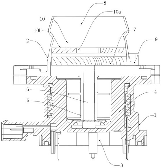
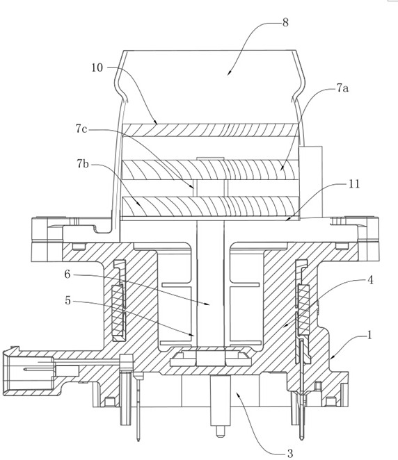
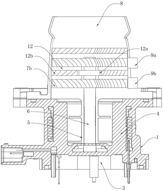
[0008] In order to solve the technical problems of self-priming lag, large instantaneous noise, and slow flow rate of cooling water in the prior art, the present invention provides the following technical solutions: A DC electronic water pump for automobiles, including a pump body, a cover body, and an electric control board , stator, rotor, rotating shaft and impeller; the cover body is fixedly installed on the pump body, wherein the cover body is provided with a water inlet pipeline along the axis direction, and a water outlet pipeline along the tangential direction, the water inlet pipeline and the The water outlet pipelines are all connected to the inner cavity of the cover, the electric control board and the stator are encapsulated in the inner cavity of the pump body through epoxy resin glue, and the two are electrically connected, and the rotating shaft is fixed to the The other end of the pump body extends to the inner cavity of the cover. The rotor is arranged in the inner cavity of the pump and sleeved on the rotating shaft through a sleeve. The impeller is arranged in the inner cavity of the cover and sleeved on the rotating shaft. The impeller and the The rotor is fixedly connected; it also includes a first guide vane, the first guide vane includes a first central sleeve and a first set of guide vanes circumferentially arranged on the outer wall of the first central sleeve, the first The guide impeller is arranged at the intersecting joint between the water inlet pipeline and the cover body and arranged coaxially with the impeller, the outer ends of the first set of guide vanes are fixedly connected to the inner wall of the water inlet pipeline, and the first set of guide vanes are fixedly connected to the inner wall of the water inlet pipeline. A guide impeller is similar in structure to the stationary guide vane disc of the turboshaft engine; the impeller is similar in structure to the rotating working impeller of the turboshaft engine

Method used


Image

  • An automotive direct current electronic water pump
  • An automotive direct current electronic water pump
  • An automotive direct current electronic water pump

Examples


Embodiment 1

[0025] like figure 1 As shown, the present embodiment provides an automotive direct current electronic water pump, including a pump body 1, a cover body 2, an electric control board 3, a stator 4, a rotor 5, a rotating shaft 6 and an impeller 7; the cover body 2 is fixedly mounted on the pump Body 1, wherein the cover body 2 is provided with a water inlet pipeline 8 along the axial direction, and a water outlet pipeline 9 is provided along the tangential direction, and the water inlet pipeline 8 and the water outlet pipeline 9 are both communicated with the inner cavity of the cover body 2 , the electric control board 3 and the stator 4 are encapsulated in the inner cavity of the pump body 1 through epoxy resin glue, and the two are electrically connected, and the rotating shaft 6 is fixed to the pump body 1 along the axis of the stator 4 with one end , the other end extends to the inner cavity of the cover body 2, the rotor 5 is set in the inner cavity of the pump body 1 and ...

Embodiment 2

[0030] like figure 1 As shown, in order to get closer to the impeller structure of the turboshaft engine and further improve the cooling water transfer efficiency and flow rate, the inner diameter of the water inlet pipeline 8 and the connection with the cover body 2 in this embodiment is equal to the outer diameter of the impeller 7; The structure is the same as that of Embodiment 1, and will not be repeated here.

Embodiment 3

[0032] preferred, such as figure 1 As shown, in order to further reduce the noise level of the automotive DC electronic water pump provided in this embodiment, considering that the high-speed cooling water will also generate some noise when it first contacts the first guide impeller 10, the first set of guide vanes in this embodiment It is made of vulcanized rubber material. On the one hand, the vulcanized rubber can work stably for a long time. On the other hand, it has certain elasticity and can effectively absorb impact force, thereby further reducing the level of instantaneous noise.


PUM


Abstract

The invention discloses a direct flow electronic water pump of an automobile and belongs to the technical field of new energy automobile electronic water pumps. The direct flow electronic water pump specifically comprises a pump body, a cover body, an electronic control panel, a stator, a rotor, a rotating shaft and a vane wheel and further comprises a first guiding vane wheel. The first guiding vane wheel comprises a first central sleeve and a first set of guiding vanes, wherein the first set of guiding vanes are arranged on the outer side wall in the circumferential direction. The first guiding vane wheel is arranged on a water inlet pipe and is coaxial with the vane wheel. The outer ends of the first set of guiding vanes are all fixedly connected to the inner wall of the water inlet pipe. By means of the direct flow electronic water pump, on one hand, the water inlet pipe is provided with the guiding vane wheels, the negative pressure can be formed in an inner chamber of the cover body conveniently, and the self suction performance is rapidly achieved; on the other hand, before entering the cover body, cooling water is forced to enter the inner chamber of the cover body along the vanes of the guiding vane wheels, and the problem that the high-speed cooling water directly impacts the vane wheels to generate noise is avoided; in addition, the direct flow electronic water pumpis benefitted by the mature turboshaft engine vane wheel structure design, and cooling liquid can achieve the faster delivery effect under the effect of the first guiding vane wheel and the vane wheels; and the cooling water is higher in flow speed.

Description

technical field [0001] The invention relates to the technical field of electronic water pumps for new energy vehicles, in particular to a DC electronic water pump for vehicles. Background technique [0002] With the development of automotive electronic technology, automotive electronic systems are becoming more and more complex, and the correlation with functional safety is constantly increasing. Any failure of safety-related software and hardware may bring serious consequences. When a product fails or fails, it can Whether to continue to ensure the safety of the system has become a topic of concern to everyone. Among them, the most concerned thing is the reliable heat dissipation of the internal system; electronic water pumps are widely used in automobile heat dissipation circulation systems, and provide circulation flow power of heat dissipation medium in the heat dissipation circulation system ;After the car is started, the electronic control components will generate a lo...

Claims


Application Information

Patent Timeline
Patent Type & Authority Patents(China)
IPC IPC(8): F04D13/06F04D29/22F04D29/18F04D29/44F04D29/66F01P5/10
CPCF01P5/10F01P2005/125F04D13/06F04D29/185F04D29/22F04D29/445F04D29/669
Inventor 李娟王锋沈伟刘建军
Owner SHANGHAI JIDING IND CO LTD
Learn More