
A sealing device for steam pipes that can be temporarily sealed by using leakage medium

A temporary sealing and steam pipeline technology, which is applied in the direction of pipe components, pipes/pipe joints/fittings, mechanical equipment, etc., can solve the problems of fastening bolts loosening, slow installation speed, and pipeline air leakage, etc., to improve installation stability and Sealing, avoiding burns to operators, and preventing steam leakage

Active Publication Date: 2020-07-10
济宁高新公用事业发展股份有限公司
View PDF4 Cites 0 Cited by
  • Summary
  • Abstract
  • Description
  • Claims
  • Application Information

AI Technical Summary

Problems solved by technology

[0003] The end flange is used to connect the cover, and the bolts and nuts need to be screwed one by one to fix the connection. This method is slow in installation speed. After installation and sealing, the medium flow rate in the steam pipeline is fast, and the cover will be damaged during operation. It brings a relatively large impact force. After a long time, the fastening bolts will become loose. In addition, the sealing ring will also fail due to oxidation or aging, which will cause air leakage in the pipeline. It will take a certain amount of time for the maintenance personnel to come to repair During this period, there will be a large amount of leakage. The leakage will burn the operator due to the high temperature of the steam, and it is also very likely to cause dangerous accidents such as explosion. When the maintenance personnel come to repair, they need to remove the bolts and nuts one by one before sealing. replacement and maintenance

Method used


Image

  • A sealing device for steam pipes that can be temporarily sealed by using leakage medium
  • A sealing device for steam pipes that can be temporarily sealed by using leakage medium
  • A sealing device for steam pipes that can be temporarily sealed by using leakage medium

Examples


Embodiment Construction

[0033] The following will clearly and completely describe the technical solutions in the embodiments of the present invention with reference to the accompanying drawings in the embodiments of the present invention. Obviously, the described embodiments are only some, not all, embodiments of the present invention. Based on the embodiments of the present invention, all other embodiments obtained by persons of ordinary skill in the art without making creative efforts belong to the protection scope of the present invention.

[0034] In the description of the present invention, it should be noted that unless otherwise specified and limited, the terms "connected" and "connected" should be understood in a broad sense, for example, it can be a fixed connection, a detachable connection, or an integral Ground connection; it can be mechanical connection or electrical connection; it can be direct connection or indirect connection through an intermediary. Those of ordinary skill in the art ...


PUM


Abstract

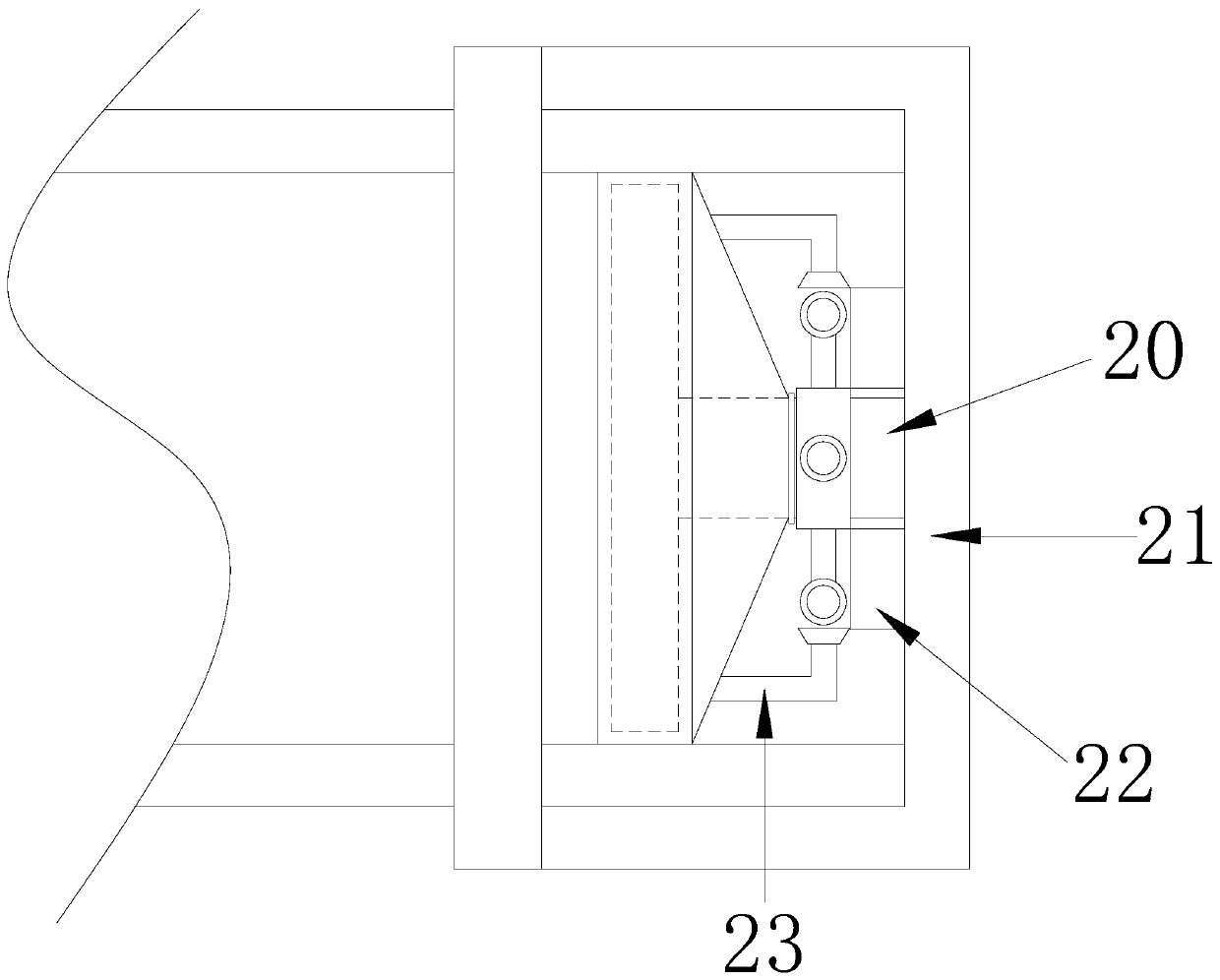
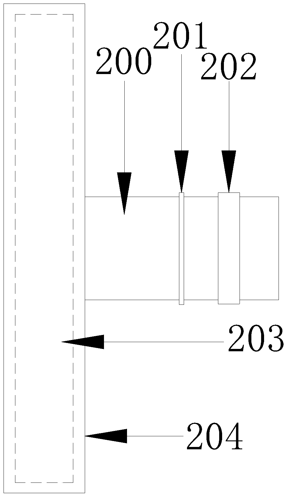
The invention discloses a sealing device for a steam pipeline capable of being temporarily sealed by using a leakage medium. The sealing device structurally comprises a pipeline and a sealing plug cover, wherein the sealing plug cover is arranged at one end of the pipeline; and the sealing plug cover comprises an inner supporting frame, a sealing cover, a temporary sealing mechanism and a gas collecting mechanism, wherein the inner supporting frame is fixed at the center of the inner end surface of the sealing cover. Compared with the prior art, the sealing device has the advantages that powerful sucking plates can be tightly adsorbed on the outer wall of the pipeline through hydraulic rods, the pressure of inner springs on arc-shaped clamping plates can enable arc-shaped clamping pads totightly clamp the pipeline, so that the sealing cover is firmly plugged into the pipeline, and the installation stability and the sealing performance of the sealing cover are improved; and steam leakage can be prevented to a great extent before maintenance personnel to maintain, the operators can be prevented from being scalded by the the high-temperature steam, dangerous accidents such as explosion can be avoided, and rapidly disassembling and maintaining can be realized during maintenance by the maintenance personnel.

Description

technical field [0001] The invention relates to the technical field of electric power engineering, in particular to a sealing device for a steam pipe which can be temporarily sealed by using a leakage medium. Background technique [0002] Existing seals for steam pipes mainly use plugs or end flanges to connect the caps to achieve sealing. [0003] The end flange is used to connect the cover, and the bolts and nuts need to be screwed one by one to fix the connection. This method is slow in installation speed. After installation and sealing, the medium flow rate in the steam pipeline is fast, and the cover will be damaged during operation. It brings a relatively large impact force. After a long time, the fastening bolts will become loose. In addition, the sealing ring will also fail due to oxidation or aging, which will cause air leakage in the pipeline. It will take a certain amount of time for the maintenance personnel to come to repair During this period, there will be a ...

Claims


Application Information

Patent Timeline
Patent Type & Authority Patents(China)
IPC IPC(8): F16L55/168
CPCF16L55/1612
Inventor 张冰冰
Owner 济宁高新公用事业发展股份有限公司
Learn More