Projector for matrix system and adjusting method

A projector and matrix technology, applied in the field of projectors, can solve the problems of affecting image projection quality, low control strength, and inability to adjust left and right angles, and achieve the effects of improving projection quality, improving airtightness, and facilitating movement.

Pending Publication Date: 2019-02-15
大连国晨科技有限公司
View PDF0 Cites 3 Cited by
  • Summary
  • Abstract
  • Description
  • Claims
  • Application Information

AI Technical Summary

Problems solved by technology

[0004] The projector used in the matrix system cannot adjust its left and right angles very well, and the control of its direction is low, which will affect the projection quality of the image

Method used


Image

  • Projector for matrix system and adjusting method
  • Projector for matrix system and adjusting method
  • Projector for matrix system and adjusting method

Examples


Embodiment 1

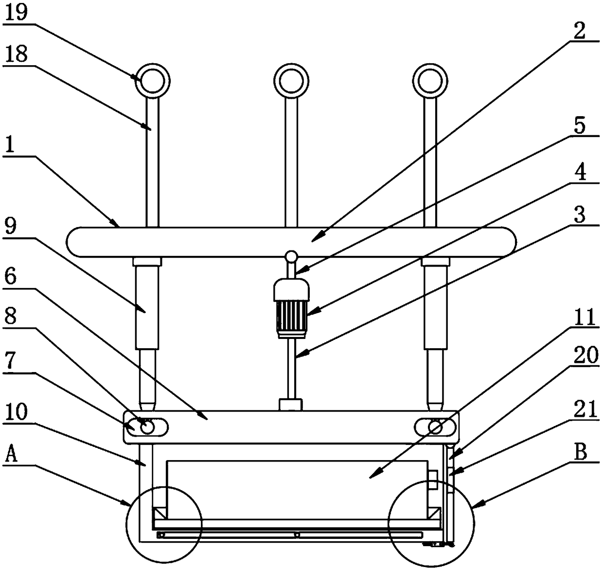
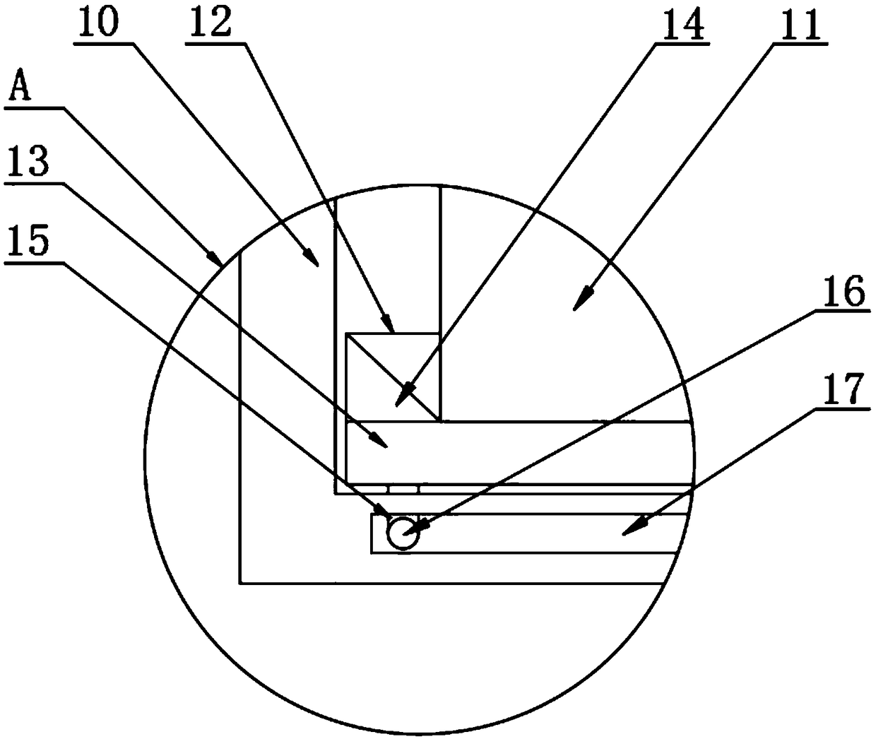
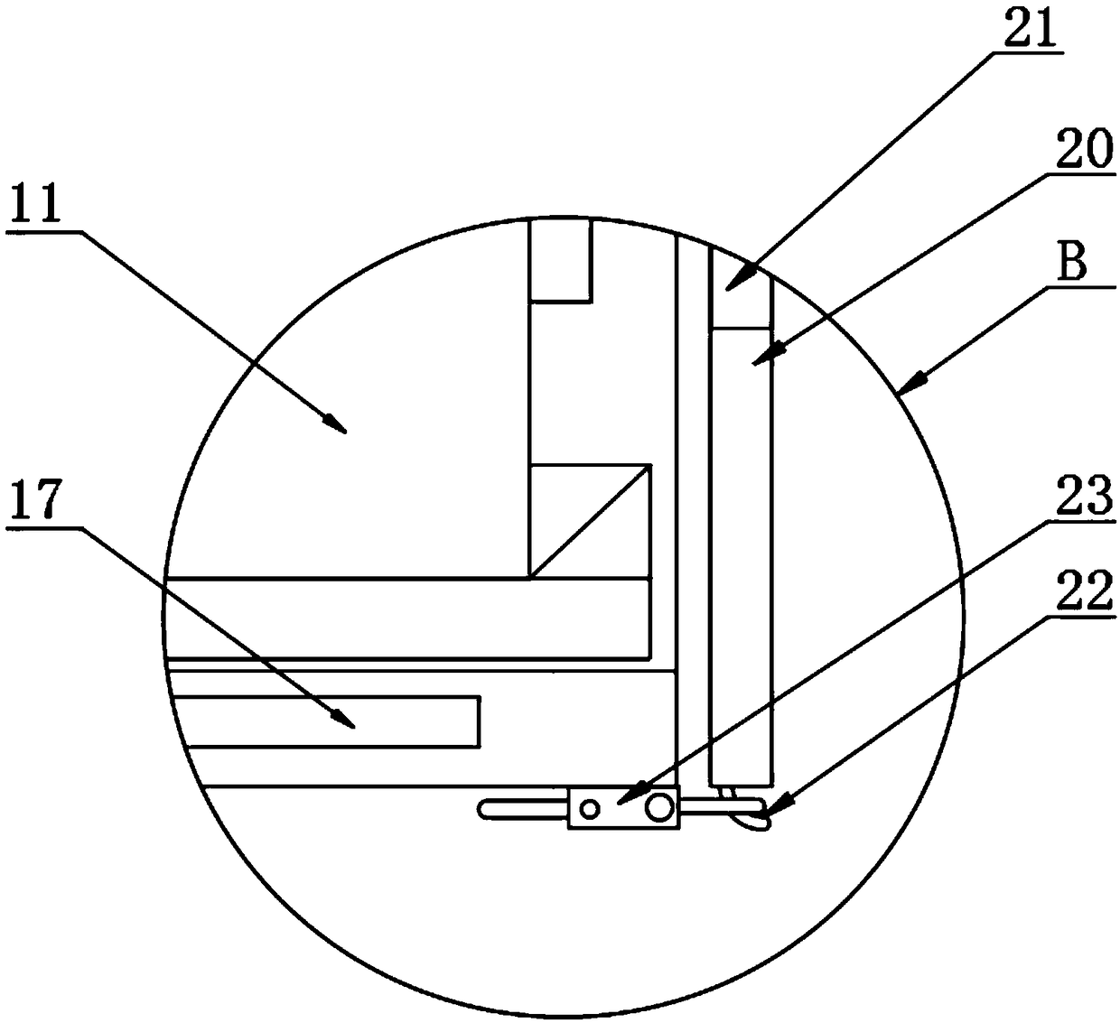
[0026] The present invention provides such Figure 1-4 The shown projector for a matrix system includes an adjusting device 1, the adjusting device 1 includes a top plate 2, the bottom of the top plate 2 is provided with a rotating shaft 3, and the top of the rotating shaft 3 is provided with a servo motor 4, and the servo The output shaft of the motor 4 is fixedly connected with the rotating shaft 3, the top of the servo motor 4 is provided with a push rod 5, the top of the push rod 5 is hinged with the surface of the top plate 2, and the bottom of the rotating shaft 3 is provided with an adjustment plate 6, and the adjustment plate 6 The surface is provided with a ring groove 7, and the inside of the ring groove 7 is provided with a sliding ball 8, and the sliding ball 8 is slidably connected with the ring groove 7, and the top of the sliding ball 8 is provided with an electric telescopic rod 9, and the electric telescopic rod 9 The output shaft is fixedly connected with the...

Embodiment 2

[0036] A method for adjusting a projector for a matrix system, comprising the projector for a matrix system, further comprising the following steps:

[0037] S1: hang the fixed object on the fixed ring 19;

[0038] S2: Open the servo motor 4 and the electric telescopic rod 9, the servo motor 4 drives the adjustment plate 6 to rotate through the rotating shaft 3, and at the same time, the sliding ball 8 slides inside the ring groove 7, and the placement box 10 performs multi-directional rotation adjustment;

[0039] S3: multiple electric telescopic rods 9 drive the adjustment plate 6 to rise through the sliding ball 8, adjust the horizontal height of the four corners of the adjustment plate 6, and adjust the left and right angles thereof.


PUM


Abstract

The invention discloses a projector for a matrix system and an adjusting method. The projector for the matrix system comprises an adjusting device, the adjusting device comprises a top plate, a rotation shaft is arranged at the bottom of the top plate, a servo motor is arranged on the top of the rotation shaft, and an output shaft of the servo motor is fixedly connected with the rotation shaft; atop rod is arranged on the top of the servo motor, and the top end of the top rod is hinged to the surface of the top plate; an adjusting plate is arranged at the bottom of the rotation shaft, annulargrooves are formed in the surface of the adjusting plate, a sliding ball is arranged in each annular groove, and the sliding balls are slidably connected with the annular grooves; an electric telescopic rod is arranged on the top of each sliding ball, an output shaft of each electric telescopic rod is fixedly connected with the corresponding sliding ball, and the top end of each electric telescopic rod is fixedly connected with the top plate; and a containing box is arranged at the bottom of the adjusting plate. According to the projector for the matrix system and the adjusting method, the horizontal height of the four corners of the adjusting plate can be adjusted through the adjusting device, the left angle and the right angle of the adjusting plate can be effectively adjusted, the direction control force is increased, and the image projection quality is improved.

Description

technical field [0001] The invention relates to the technical field of projectors, in particular to a projector for a matrix system and an adjustment method. Background technique [0002] A projector is an optical instrument that uses optical elements to enlarge the contour of a workpiece and projects it onto a video screen. It can use transmitted light for contour measurement, and can also use reflected light to measure the surface shape of a non-through hole and observe the surface of a part. Projection The instrument is especially suitable for measuring complex contours and small workpieces, such as watch parts, stamping parts, electronic components, templates, molds, threads, gears and forming tools, etc. It has high inspection efficiency and is easy to use. It is widely used in measuring rooms and production workshops. This is especially true for the instrumentation and watch industry. [0003] A projector, also known as a projector, is a device that can project images...

Claims


Application Information

Patent Timeline
Patent Type & Authority Applications(China)
IPC IPC(8): F16M11/04F16M11/08F16M13/02G03B21/14
CPCF16M11/046F16M11/045F16M11/08F16M13/02G03B21/145
Inventor 姚景国王丽
Owner 大连国晨科技有限公司
Why Eureka
Try Eureka