Dewatering and drying device for textile cloth

A technology for dehydrating and drying cloth, applied in drying, drying machines, heating devices, etc., can solve the problems of simple structure, single function, low drying efficiency, laborious and laborious, etc., to achieve simple structure, improve efficiency, and eliminate wrinkles Effect

Inactive Publication Date: 2019-02-15
利辛县盈德纱网有限公司
View PDF5 Cites 10 Cited by
  • Summary
  • Abstract
  • Description
  • Claims
  • Application Information

AI Technical Summary

Problems solved by technology

[0003] However, the existing textile cloth dehydration drying device has a simple structure and a single function. The cloth is dehydrated and dried through centralized stacking. The drying efficiency is low, and the drying effect is not good. At the same time, most textile cloth dehydration drying devices , only a single air blower and drying plate are used, and the cloth cannot be dried quickly, and it is laborious to use

Method used


Image

  • Dewatering and drying device for textile cloth
  • Dewatering and drying device for textile cloth
  • Dewatering and drying device for textile cloth

Examples


Embodiment 1

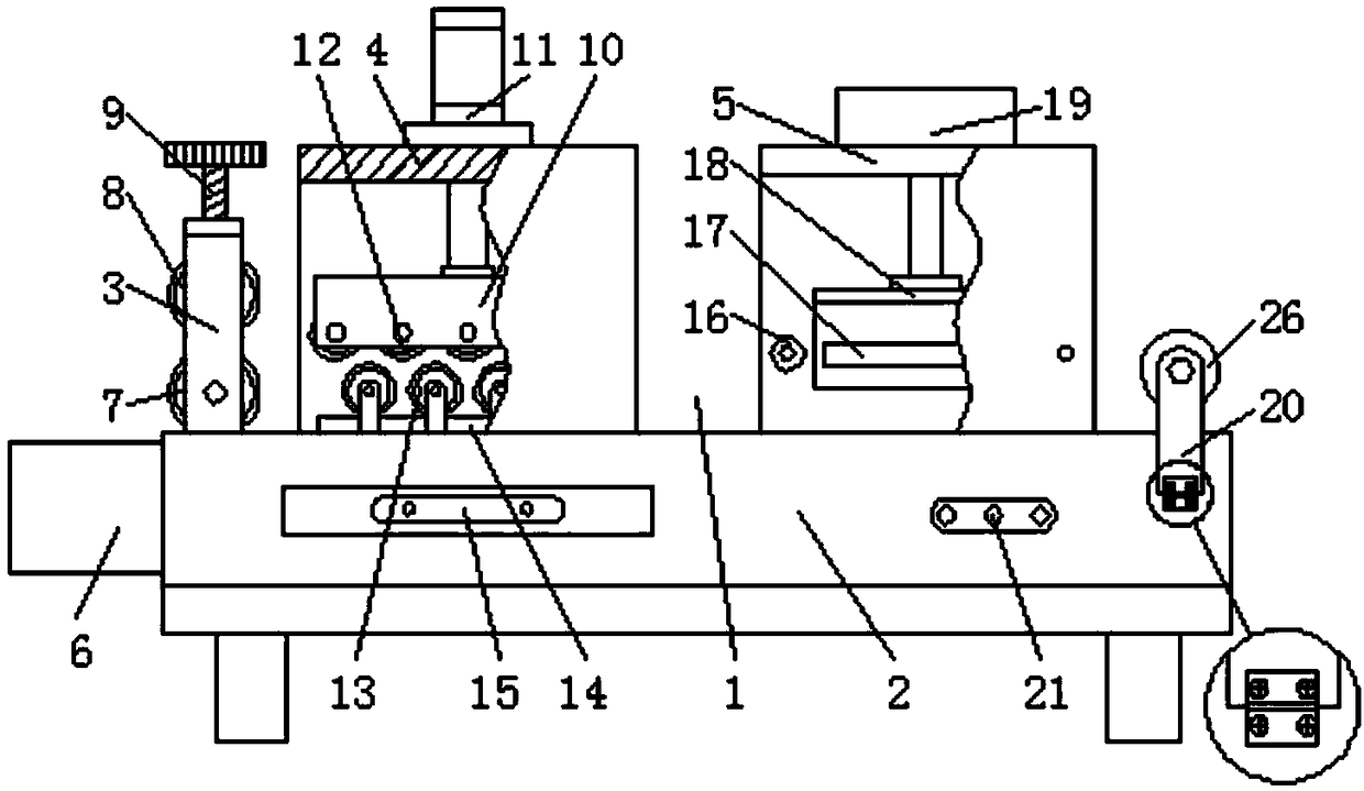
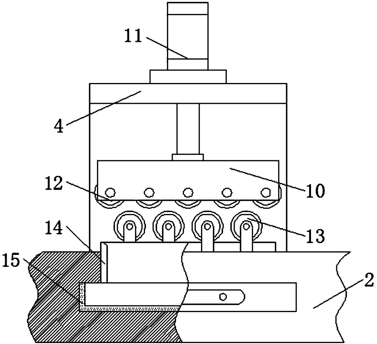
[0024] Embodiment one, with reference to Figure 1-5 , a dehydration and drying device for textile cloth, comprising a dehydration and drying device body 1 and a drying box 5, the bottom of the dehydration and drying device body 1 is provided with a workbench 2, and one side of the workbench 2 is bolted to place The box 6 and the top of the workbench 2 are symmetrically welded with a dehydration box 4 and a drying box 5. The interior of the dehydration box 4 is provided with a lifting plate 10, and the top of the dehydration box 4 is fixedly connected with a cylinder 11 used in conjunction with the lifting plate 10. The lifting plate The bottom of 10 is uniformly rotated and connected with a plurality of first dewatering rollers 12, and the bottom of dewatering box 4 is evenly rotated and connected with a plurality of second dewatering rollers 13. The inside of workbench 2 is slidingly embedded with a drain pan 15 used in conjunction with dewatering box 4. 4. The water guide p...

Embodiment 2

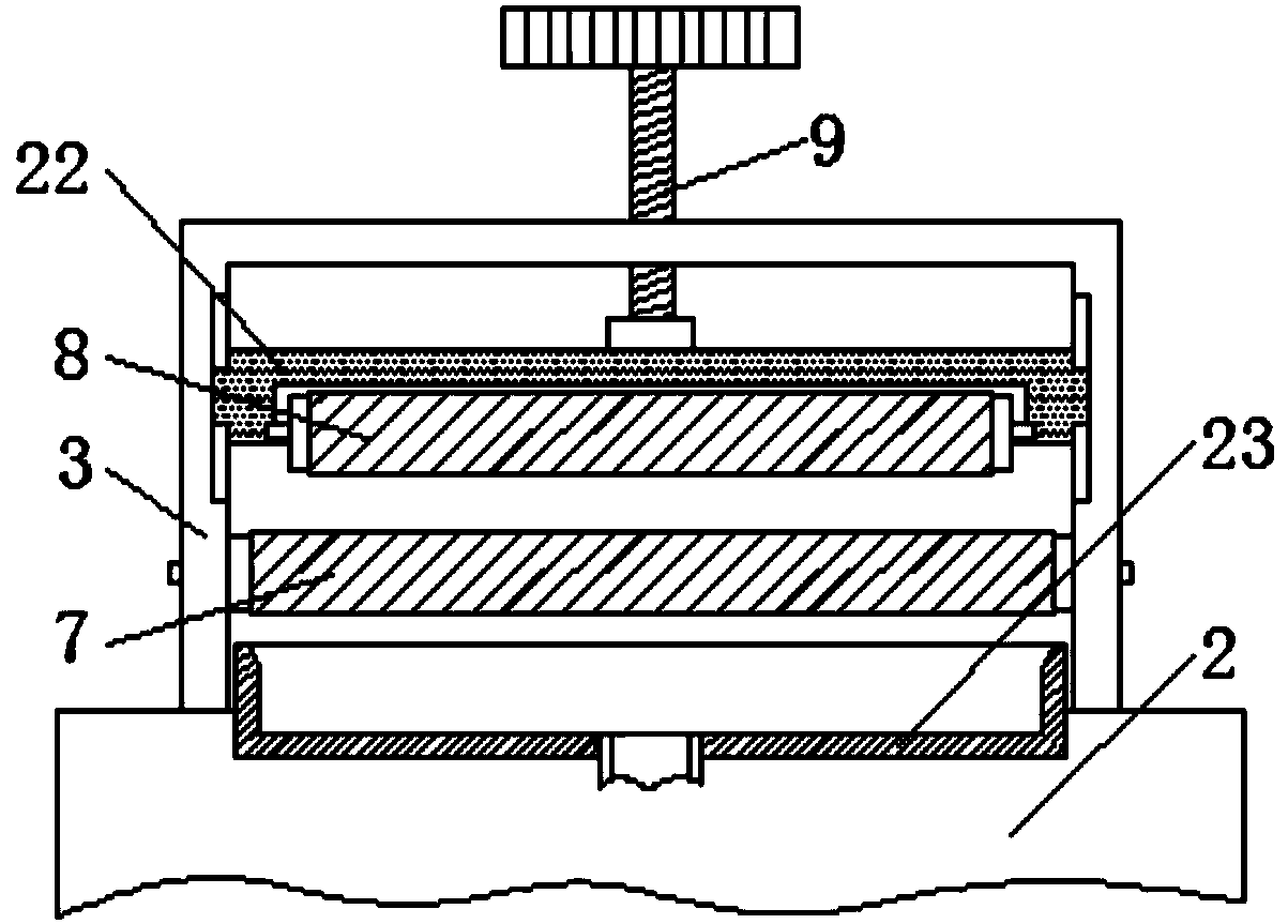
[0025] Embodiment two, refer to figure 1 and figure 2 , the top of the workbench 2 is located on one side of the dehydration box 4 and is welded with a fixed bracket 3, the inside of the fixed bracket 3 is connected with the first squeeze roller 7 through the rotation of the rotating shaft, and the top of the workbench 2 is located under the fixed bracket 3. The water receiving box 23, the water receiving box 23 communicates with the drain pan 15 through a conduit, the inside of the fixed bracket 3 is located above the first squeeze roller 7 and is slidably connected with a slide plate 22, and the bottom of the slide plate 22 is connected with a second squeeze through a rotating shaft. The top of the roller 8 and the slide plate 22 is connected with a screw 9 that runs through the fixed bracket 3. The screw 9 can be rotated to adjust the height of the slide plate 22 in the fixed support 3, so that the height of the slide plate 22 can be adjusted according to the thickness of ...

Embodiment 3

[0026] Embodiment three, refer to figure 1 and Figure 4 , the inside of the drying box 5 is fixedly connected with an air supply pan 18 above the drying plate 17, and the top bolt of the drying box 5 is fixedly connected with a fan body 19 used in conjunction with the air supply pan 18, and the fan body 19 passes through the air supply pipe. 24 communicates with the air supply disc 18, the cross section of the air supply disc 18 is an inverted C-shaped structure, the wind that can be sent into the fan body 19 is circular and evenly sent to the textile cloth in the drying box 5, and the upper drying plate 17 is matched. The textile cloth entering the inside of the drying box 5 can be dried rapidly.


PUM


Abstract

The invention discloses a dewatering and drying device for textile cloth. The dewatering and drying device comprises a dewatering and drying device body and a drying box, wherein a workbench is arranged at the bottom of the dewatering and drying device body, a placing box is fixed on one side of the workbench through bolts, and the top of the workbench is symmetrically provided with a dewatering box and the drying box in a welded mode. According to the dewatering and drying device, the dewatering and drying device body is simple in structure, reasonable in design, and capable of efficiently conducting dewatering treatment on the textile cloth, a lifting plate which is in sliding connection in the dewatering box can be used for squeezing the textile cloth between a first dewatering roller and a second dewatering roller in a staggered mode under pushing of an air cylinder, and the combined first dewatering roller and the second dewatering roller can generate squeezing force so as to squeeze out water content in the textile cloth. According to the device, the structure can be used for carrying out dewatering treatment on the textile cloth with high efficiency, meanwhile, the rotatingdewatering rollers can be used squeezing the cloth to be flat in a rotating mode, so that wrinkles of the textile cloth can be eliminated.

Description

technical field [0001] The invention relates to the technical field of dehydration and drying devices for textile cloth, in particular to a dehydration and drying device for textile cloth. Background technique [0002] The English full name of drying equipment is Drying equipment, which refers to the combination of a series of mechanical equipment to dry the moisture on the surface of objects or other liquids through certain technical means. The current popular drying technologies are mainly ultraviolet drying, infrared drying, electromagnetic Drying and hot air drying have their own characteristics and are widely used in the drying of various mechanical equipment and food. [0003] However, the existing textile cloth dehydration drying device has a simple structure and a single function. The cloth is dehydrated and dried through centralized stacking. The drying efficiency is low, and the drying effect is not good. At the same time, most textile cloth dehydration drying devi...

Claims


Application Information

Patent Timeline
Patent Type & Authority Applications(China)
IPC IPC(8): F26B13/00F26B13/28F26B13/10F26B23/06F26B21/00
CPCF26B13/00F26B13/10F26B13/28F26B21/004F26B23/06
Inventor 张忙英
Owner 利辛县盈德纱网有限公司
Why Eureka
Try Eureka