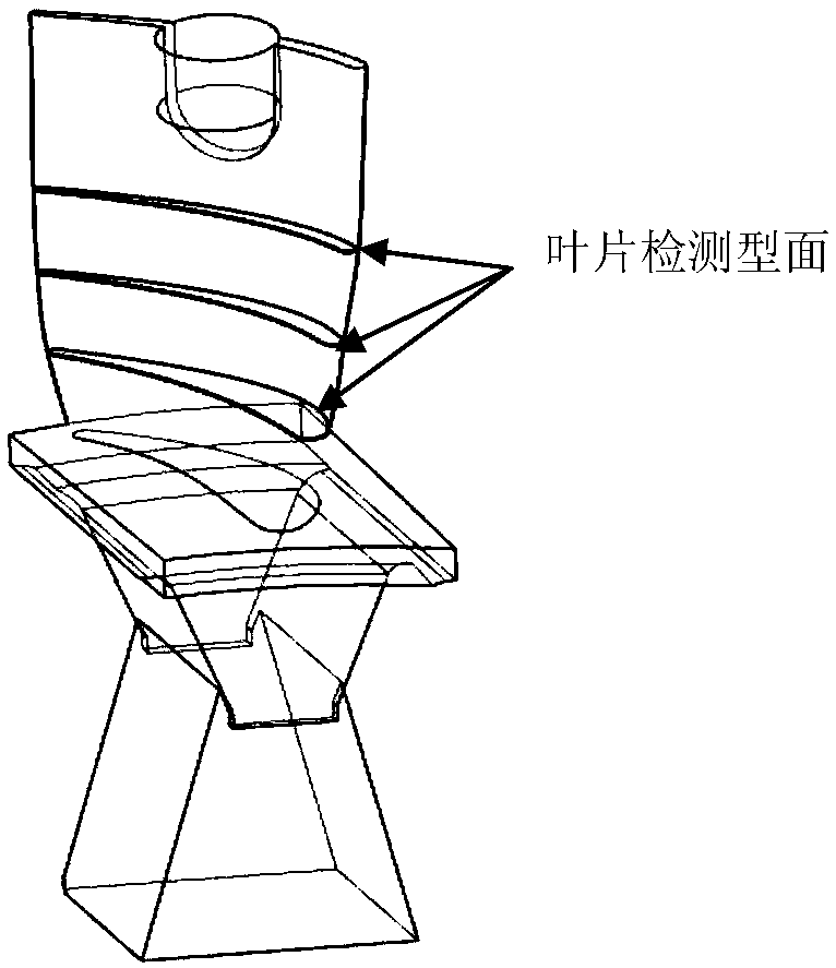
[0027] The embodiments of the present invention will be described in detail below with reference to the accompanying drawings, but the present invention may be implemented in a variety of different ways defined and covered below.
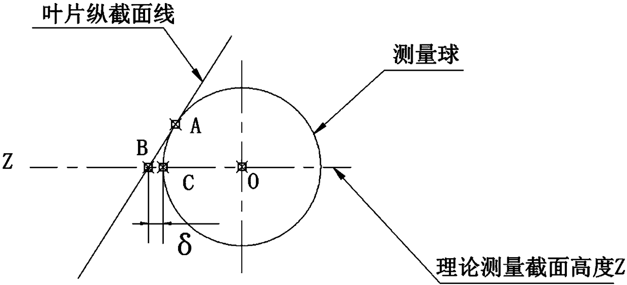
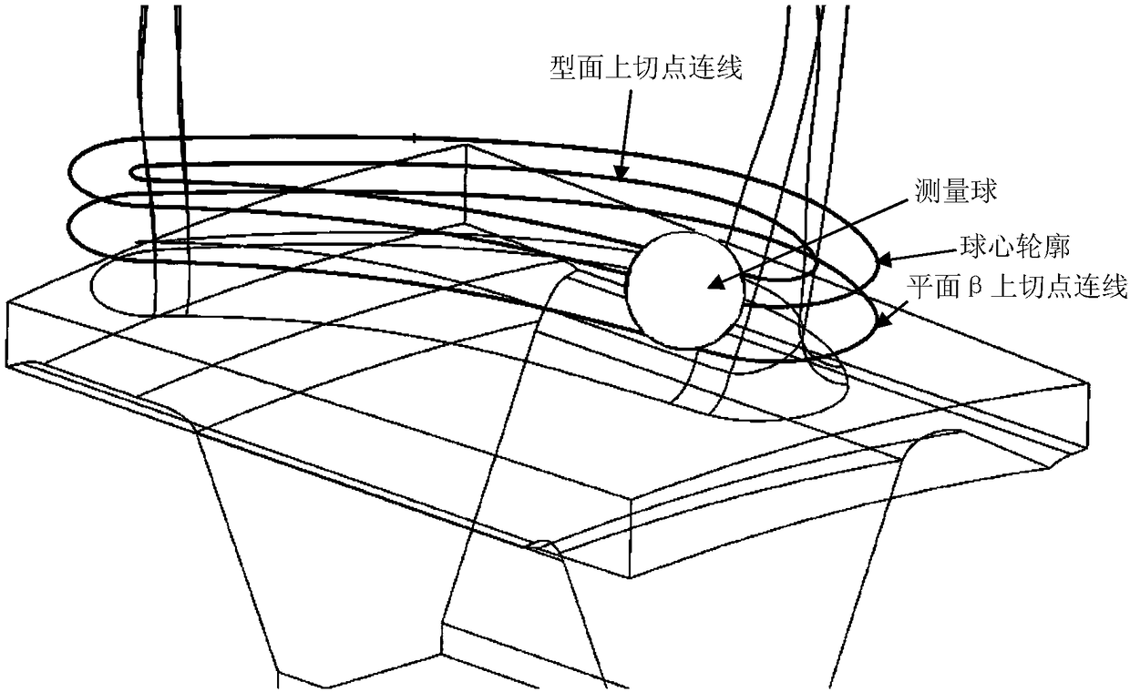
[0028] image 3 It is a schematic diagram of the measurement of the cross-sectional profile size of the turbine blade in the preferred embodiment of the present invention; Figure 4 It is a two-dimensional schematic diagram of theoretical leaf profile compensation in a preferred embodiment of the present invention; Figure 5 It is a schematic diagram of the theoretical blade shape compensation rolling ball (surface rounding operation) of the preferred embodiment of the present invention; Image 6 It is a three-dimensional schematic diagram of measuring radius compensation in a preferred embodiment of the present invention; Figure 7 It is a two-dimensional schematic diagram of measuring radius compensation in a preferred embodiment of the present invention.
[0029] Such as image 3 , Figure 4 , Figure 5 , Image 6 with Figure 7 As shown, the method for measuring the profile size of the turbine blade section of this embodiment uses the spherical head radius of a three-coordinate measuring instrument to supplement and reversely derive the profile size of the turbine blade section, including the following steps: using three-dimensional modeling; The theoretical blade profile curve of the profile height; the theoretical blade profile profile curve is constructed after radius compensation; the theoretical blade profile profile curve and the theoretical blade profile compensation profile curve are compared and evaluated to obtain the theoretical error value; three Coordinate measurement of the actual profile profile curve of the predetermined profile height of the turbine blade to be measured; through the theoretical error value and radius compensation, the actual profile size of the turbine blade section is obtained by reverse deduction. The method for measuring the profile size of the turbine blade section of the present invention uses three-dimensional modeling to simulate and construct a theoretical blade profile curve of a standard turbine blade at a predetermined profile height; then simulate the measuring ball measurement process of a three-coordinate measuring instrument to construct the theoretical blade Type compensation profile curve, through the comparison and evaluation of the theoretical blade profile profile curve and the theoretical blade profile compensation profile curve, the theoretical error value is obtained as a correction reference for the measured value of the subsequent turbine blade to be measured at the predetermined profile height; using a three-coordinate measuring instrument Perform actual measurement of the profile size of the turbine blade to be measured at the predetermined profile height, obtain the actual profile profile curve, and then perform radius compensation on the profile profile of the actual profile curve and combine the theoretical error value to obtain the actual turbine blade Section profile size. The whole measurement process is simple, with high work efficiency and high measurement accuracy. It is suitable for measuring the profile size of various types of precision casting turbine blades.
[0030] In this embodiment, the method for constructing the theoretical airfoil profile curve is: constructing the theoretical airfoil profile curve using the design parameters of the airfoil profile curve with a predetermined profile height. The theoretical blade profile curve is directly simulated and constructed in accordance with the design requirements, and will not be affected by various environmental factors of the actual turbine blade to ensure the accuracy of subsequent data acquisition.
[0031] Such as image 3 , Figure 4 with Figure 5 As shown, in this embodiment, the construction method of the theoretical blade compensation contour curve is: let the measuring sphere radius of the three-coordinate measuring instrument be r, the predetermined profile height is z, and the predetermined profile height z goes up or down r Construct a plane β on the distance; control the height of the center of the measuring ball to keep the height constant as z for profile measurement, keep the measuring ball tangent to the standard turbine blade profile and plane β, and the center of the measuring ball is projected on the plane β In order to measure the tangent point between the ball and the plane β, the tangent point between the measuring ball and the standard turbine blade is the actual contact point between the measuring ball and the profile. Simulate a virtual plane β at a distance r in the height direction of the predetermined profile height z to form the tangent plane of the measuring ball in two directions, and find the measurement by the tangent point of the measuring ball on the plane β The projected position of the center of the sphere on the plane β, so that the position of the center of the measurement sphere on the two-dimensional plane of the predetermined profile height z can be derived in reverse. The actual measuring contact position of the measuring ball on the turbine blade is constructed by the tangent point of the measuring ball and the turbine blade profile.
[0032] Such as image 3 , Figure 4 with Figure 5 As shown, in this embodiment, the rolling ball operation is performed on the profile of the measuring ball and the plane β and the standard turbine blade, and the connection of the tangent point of the measuring ball motion track on the plane β is the center of the measuring ball on the plane β. Projection contour line; the tangent point connection of the measuring ball motion track on the standard turbine blade profile is the contact contour line of the actual contact point of the measuring ball and the profile surface; the projection contour line can be back projected to the plane of Z height. Measure the contour of the ball center. The mutual projection relationship between the plane β and the plane where the height of Z is located, as well as the simulation of the walking measurement of the measuring ball, so as to obtain the contact contour line of the actual contact point and the contour line of the measuring ball center, as the basic theory for obtaining the theoretical error value Data value.
[0033] Such as image 3 , Figure 4 with Figure 5 As shown, in this embodiment, when the blade profile is measured at a constant height to a standard turbine blade at a predetermined profile height, according to the principle of radius compensation, the center profile of the measuring sphere is moved toward the standard axis along the measuring rod of the three-coordinate measuring instrument. The direction of the turbine blade is offset by the sphere radius r to obtain the theoretical blade profile compensation profile curve; compare and evaluate on a two-dimensional plane with a predetermined profile height to obtain the theoretical blade profile compensation profile curve and the theoretical blade profile profile curve on the two-dimensional plane The difference. The theoretical airfoil radius compensation on the two-dimensional plane is carried out through the basic theoretical data values obtained by analog measurement, so as to obtain the theoretical airfoil compensation contour curve, and the theoretical airfoil compensation contour curve and the theoretical airfoil contour curve are compared to obtain two The theoretical difference between the authors and obtain the theoretical error value.
[0034] Such as image 3 , Figure 4 with Figure 5 As shown, in this embodiment, the theoretical error value is obtained by using the theoretical blade profile compensation profile curve and the theoretical blade profile profile curve.
[0035] Such as Image 6 with Figure 7 As shown, in this embodiment, the turbine blade to be measured is clamped and fixed to a predetermined profile height. The blade profile of the turbine blade to be measured is measured at a constant height, and the measured profile curve is obtained, and the actual blade profile compensation profile is obtained through radius supplement. Curve, the actual blade profile compensation contour curve is corrected and compensated by the theoretical error value to obtain the actual turbine blade section contour size. Through the actual clamping and fixing of the turbine blade to be measured on the three-dimensional measuring instrument, the actual measurement of the predetermined profile height of the turbine blade to be measured is carried out to obtain the actual measured blade profile curve, and the actual blade profile is obtained by supplementing the radius of the two-dimensional plane Compensation contour curve, the actual blade profile compensation contour curve is corrected and compensated by the theoretical error value, so as to obtain the actual sectional contour size of the turbine blade.
[0036] In this embodiment, the probe of the three-coordinate measuring instrument includes a measuring rod and a measuring ball, and the measuring ball is a measuring sphere or a measuring hemisphere. When the measuring ball is used as the measuring ball, the contact area of the measuring ball is large. When the relative position of the profile and the probe is fixed, the measuring range of the measuring ball is wider and the measuring angle is larger. When the measuring ball adopts a measuring hemisphere, the radial size of the measuring hemisphere can be consistent with the radial size of the measuring rod, which can effectively reduce the radial size of the measuring ball. The smaller the radial size of the measuring ball, the greater the error caused by the radius compensation. It is small, which can improve the measurement accuracy; in addition, reducing the radial size of the measuring ball can also reduce the interference during the measurement, and avoid the error caused by the measuring ball accidentally contacting other parts when it contacts the target position. The measuring rod needs to be rigid to ensure that the amount of bending during the measurement is minimized. In addition to stainless steel, the measuring rod can also be a tungsten carbide rod, which has high rigidity and is convenient for small diameter and oversized designs. The measuring rod can also be a ceramic rod, which is much lighter than tungsten carbide due to its rigidity due to the steel rod. When the measuring rod adopts a ceramic rod, the measuring head is prone to collision and broken, so additional collision protection is required for the measuring head. The extremely light weight carbon fiber is an inert material. The combination of this feature and a special resin matrix can have excellent protection and excellent vibration damping performance. It can also be used as a probe material.
[0037] In this embodiment, the contact portion of the measuring ball is set as a concave portion that is recessed inward, so that the concave edge of the concave portion serves as the contact portion. By contacting the edge of the recess with the target position, the contact point can be easily determined to ensure the accuracy of the contact position, and the relationship between the position and the measuring center position of the probe is known, so the profile with the predetermined profile height can be easily obtained The actual measured value of the size.
[0038] In this embodiment, the measuring ball is a silicon nitride ball, a zirconia ball or a ruby ball. When scanning aluminum or cast iron materials, if ruby balls are used, the interaction between the two materials will cause adhesion and wear on the surface of the ruby balls during the contact process, so silicon nitride balls are required. The measuring rod adopts stainless steel rod, tungsten carbide rod or ceramic rod. Optionally, the measuring ball can also be made of tool steel, such as T8A, or quenched to a hardness of HRC55-60.
[0039] During implementation, a method for measuring the blade profile of a turbine blade is provided, as follows:
[0040] Theoretical leaf shape compensation method. The radius compensation error due to measurement interference is as figure 2 Shown: Point B is a point on the theoretical blade profile. When a constant height measurement is used (the height of the probe sphere center is unchanged), the actual measurement is obtained after the Z plane radius compensation is performed due to contact interference, which makes the actual touch point A The point is C.
[0041] Therefore, the theoretical blade compensation method is conceived as follows: According to the theoretical three-dimensional model, for the predetermined height of the theoretical blade profile, when the constant height ball probe is used to contact the blade surface to measure the profile, the actual profile profile at point C after radius compensation is calculated ( Theoretical blade profile compensation profile), which is constructed in advance using three-dimensional modeling software (such as UG software), and the profile curve is used as a reference, and compared with the actual blade measurement profile curve for evaluation (such as Image 6 with Figure 7 ).
[0042] The construction method of the theoretical blade compensation profile is as follows:
[0043] Let the measuring sphere radius of the probe be r, construct a plane β at the predetermined height z downward (or upward) r distance, when the constant height z is used for contour measurement, the probe must be tangent to the plane β, and the probe sphere center The projection on the plane β is the tangent point, and the tangent point between the probe and the blade surface is the actual contact point between the probe and the curved surface. figure 2 Point A is shown.
[0044] Therefore, the rolling ball operation (surface rounding operation) is performed on the measuring ball and the plane β and the leaf-shaped curved surface, such as Figure 5 As shown, the connection of the tangent point on the plane β (that is, the connection of the tangent point between the probe and the plane β) is the projected contour line of the probe sphere center on the plane β; The contour line of the actual contact point of the blade surface (this contour line is a three-dimensional curve).
[0045] Back-project the line of the tangent point of β on the above plane to the z-plane to measure the sphere center contour line. When measuring the blade profile at a constant height, according to the principle of radius compensation, offset the spherical center radius r inward to obtain the theoretical blade profile compensation profile curve. The outline of the two-dimensional point is like figure 2 Point C shown. The difference between the theoretical compensation profile curve and the theoretical profile profile curve can be seen on the two-dimensional plane, such as Figure 4 Shown.
[0046] The theoretical blade profile measurement compensation method eliminates the compensation error of the spherical probe radius and improves the blade measurement accuracy and qualification rate. The invention relates to a method for measuring the size of a blade, in particular to a method for compensating a blade profile error and a method for constructing a profile compensation profile. The operation is simple, the measurement accuracy is guaranteed, the qualification rate is improved, and the effect is remarkable. After testing and actual production verification, the plan is feasible. When a certain aero-engine power turbine working blade has a twisted curved surface, the profile dimension accuracy is ±0.05mm, and the torsion angle and thickness of the blade root section relative to the blade tip section are large. After adopting the theoretical leaf shape compensation method, the leaf shape is such as Figure 5 Shown. Among them, the error value of the theoretical compensation leaf profile is 0.09mm at most. By adopting this method, the measurement accuracy is guaranteed and the qualification rate is improved.
[0047] The above are only preferred embodiments of the present invention and are not used to limit the present invention. For those skilled in the art, the present invention can have various modifications and changes. Any modification, equivalent replacement, improvement, etc., made within the spirit and principle of the present invention shall be included in the protection scope of the present invention.