
Measurement system and measuring method for derating curve of LED (light-emitting diode)

A measurement system and derating technology, which is applied in the direction of heat measurement, measurement device, single semiconductor device test, etc., can solve the problems of cumbersome, impossible measurement, low test accuracy, etc., to simplify the measurement process, wide applicability, and take into account the accuracy Effect

Inactive Publication Date: 2012-07-11
TONGFANG OPTO ELECTRONICS
View PDF3 Cites 9 Cited by
  • Summary
  • Abstract
  • Description
  • Claims
  • Application Information

AI Technical Summary

Problems solved by technology

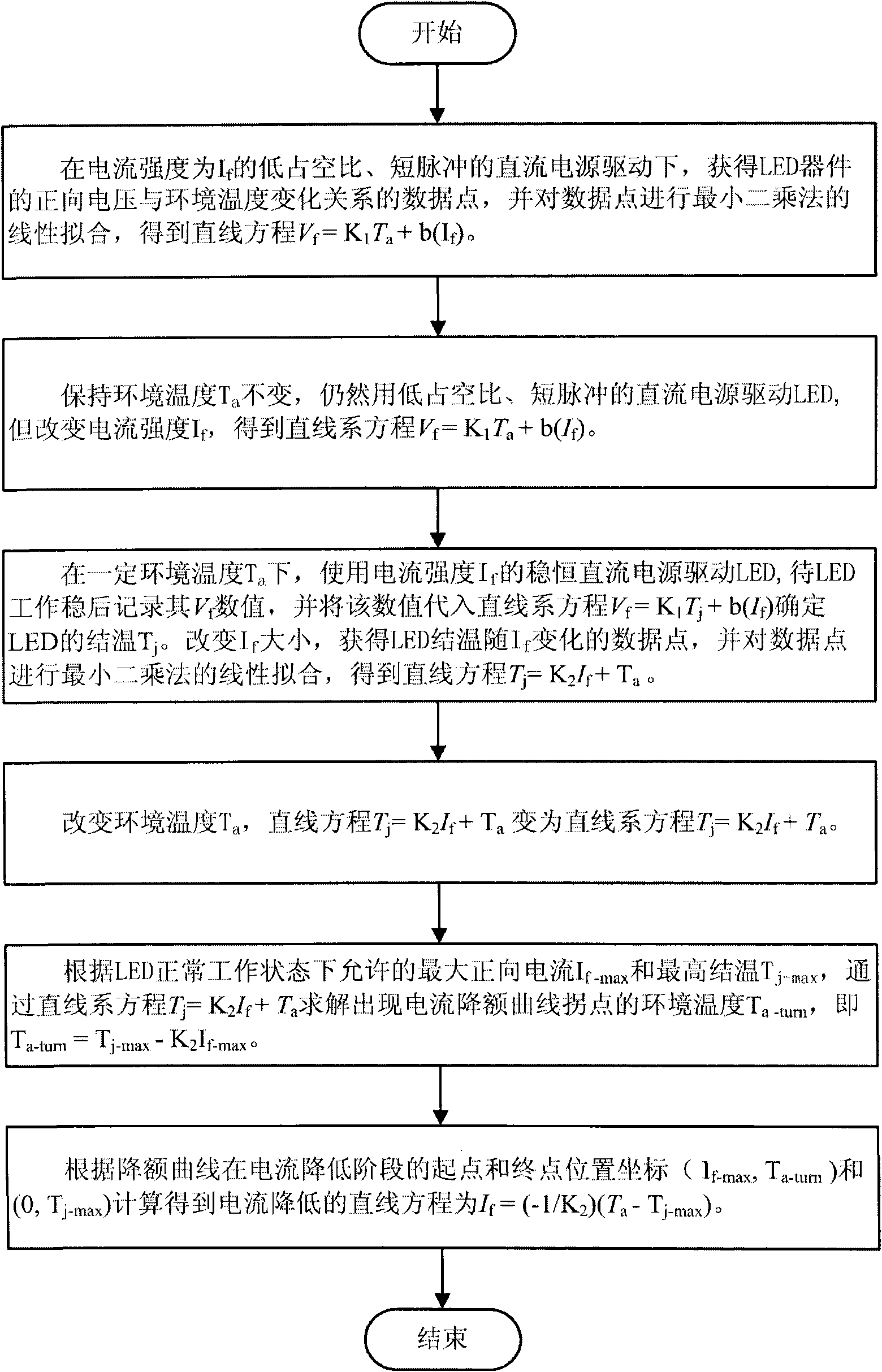
Among them, the test accuracy of methods ①, ③~⑤ is low; method ⑥ is only valid for the device form with exposed LED chips, and cannot be measured for general packaged devices or lamps; method ② has high test accuracy and a wide range of applications , but for the calculation of junction temperature under multiple current intensities, this method is more cumbersome

Method used


Image

  • Measurement system and measuring method for derating curve of LED (light-emitting diode)
  • Measurement system and measuring method for derating curve of LED (light-emitting diode)
  • Measurement system and measuring method for derating curve of LED (light-emitting diode)

Examples


Embodiment Construction

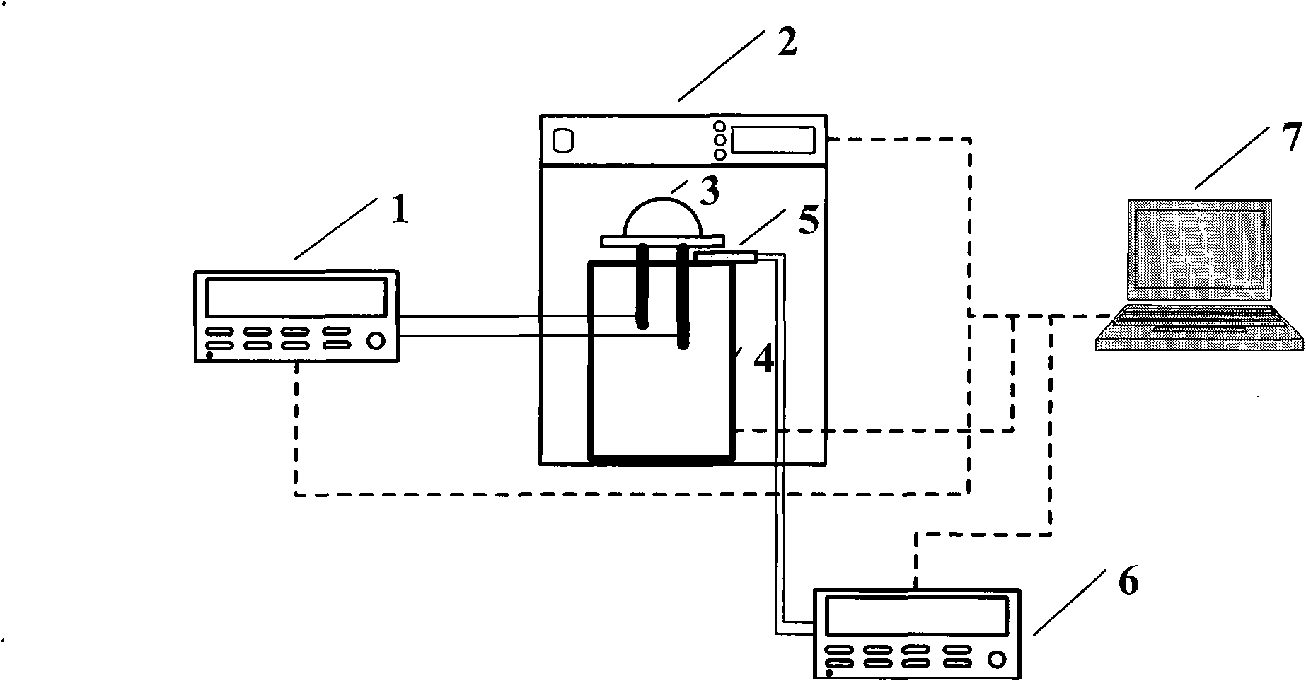
[0030] see figure 1 , The measurement system of the present invention includes a digital source meter 1, a constant temperature oven 2, a thermocouple 5, a fixture 4, a digital multimeter 6, a computer 7, and an LED chip to be tested or a packaged LED device or a lamp to be tested LED3. The LED3 to be tested, the thermocouple 5 and the fixture 4 are placed in the constant temperature oven 2 , and the LED3 to be tested and the thermocouple 5 are placed at the same position on the fixture 4 . Use the four-wire method to connect the digital source meter 1 and the LED 3 to be tested, use the four-wire method to connect the digital multimeter 6 and the thermocouple 5, and connect the digital source meter 1, the digital multimeter 6, the fixture 4 and the constant temperature oven 2 to the computer 7 respectively. Digital source meter 1 provides the forward current to drive the LED3 to be tested and measures the forward voltage at the same time. Digital source meter 1 has the functi...


PUM

PropertyMeasurementUnit
Heat resistance temperatureaaaaaaaaaa

Abstract

The invention relates to a measurement system and a measurement method for a derating curve of an LED (light-emitting diode), belonging to the technical field of detection on thermal properties of semiconductor optoelectronic devices. According to the measurement system disclosed by the invention, the LED to be tested, a thermocouple and a clamp are arranged in a constant-temperature oven, and the LED to be tested and the thermocouple are arranged in the same position on the clamp. A digital source meter is connected with the LED to be tested, and a digital universal meter is connected with the thermocouple. The digital source meter, the digital universal meter, the clamp and the constant-temperature oven are respectively connected with a computer. The digital source meter is used for providing forward current for driving the LED to be tested; the constant-temperature oven is used for providing a stable environmental temperature; the thermocouple is used for detecting the actual environmental temperature in the vicinity of the LED to the tested; the digital universal meter is used for patrol inspection on the resistance of the thermocouple; and the computer is responsible for collecting and processing related data and outputting the graphical derating curve to a user. Compared with the prior art, the measurement system and method disclosed by the invention have the advantages of high efficiency, accuracy and a wide range of applications.

Description

technical field [0001] The invention belongs to the technical field of thermal performance detection of semiconductor optoelectronic devices, in particular to a measurement system and method for LED junction temperature and current derating curves. Background technique [0002] LED is the abbreviation of English Light Emitting Diode, translated as light emitting diode. So far, the luminous efficiency of global commercial white LED products has reached about 150lm / W, which is about twice that of fluorescent lighting; while the luminous efficiency of white LEDs under laboratory conditions is as high as about 200lm / W. The service life can reach more than 50,000 to 100,000 hours. The excellent quality and huge market value of LEDs such as energy saving, environmental protection, and long life have been widely recognized all over the world. [0003] Although the electro-optic conversion efficiency of the LED is very high, a small part of the electrical energy is still converted...

Claims


Application Information

Patent Timeline
IPC IPC(8): G01R31/26G01K7/02
Inventor 马亮
Owner TONGFANG OPTO ELECTRONICS
Learn More