Supercharge Your Innovation With Domain-Expert AI Agents!

Measuring device and measuring method for unlocking angle and unlocking torque of door lock mechanism

An angle measuring device and a technology for torque measurement, which are used in measuring devices, force/torque/work measuring instruments, and torque/torsional force measurement during tightening. Complicated and other problems, to achieve the true and reliable effect of the measured data of the lock mechanism

Pending Publication Date: 2019-02-15
NANJING INST OF TECH
View PDF0 Cites 0 Cited by
  • Summary
  • Abstract
  • Description
  • Claims
  • Application Information

AI Technical Summary

Problems solved by technology

[0004] In general, an encoder is used for angle measurement, but it cannot carry torque in the measurement
If the encoder is installed at the two ends of the equipment, although there is no force, the design requirements for the measuring device are high, the installation is also complicated, and the cost is high
The door lock mechanism needs power input in the measurement, and there is resistance loading at the load end. If the power input device and the load simulation device are fixed, the installation process of the door lock mechanism is more complicated; the unlocking angle measurement, if the encoder is used at the power end To measure the rotation angle, there must be a feedback signal at the load end
If the feedback device is to monitor the action of the load end and output a signal when there is an action, then the threshold setting requirements for this action signal are high. If it is set low, the anti-interference is stronger, and the requirements for the monitoring device circuit are high. If it is set high, it will bring Angle measurement big error
In addition, due to the internal stress of the door lock mechanism, if the unlocking rotation of the power end is not fully unlocked, there will be stress release, which is manifested as intermittent rotation at the load end and short-term follow-up rotation. The power end will rely on the action feedback signal of the load end to measure the unlocking angle. There are spurious measurements

Method used


Image

  • Measuring device and measuring method for unlocking angle and unlocking torque of door lock mechanism
  • Measuring device and measuring method for unlocking angle and unlocking torque of door lock mechanism
  • Measuring device and measuring method for unlocking angle and unlocking torque of door lock mechanism

Examples


Embodiment Construction

[0025] The technical scheme of the present invention is described in detail below in conjunction with accompanying drawing:

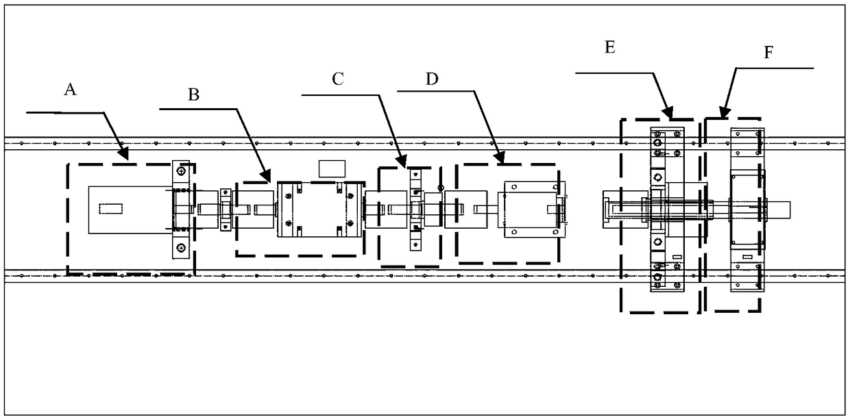
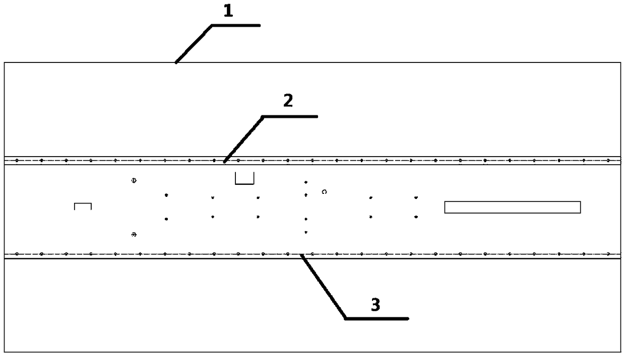
[0026] Such as figure 1 , figure 2 As shown, a device for measuring the unlocking angle and unlocking torque of a door lock mechanism includes a base 1, a first guide rail 2 and a second guide rail 3 are arranged on both sides along the length direction of the base, a power source A is arranged on the base 1, and a power source A One end of the torque testing device B is connected to one end of the torque testing device B through the first polished rod 8 and the second shaft coupling 9, and the other end of the torque testing device B is connected to the power end angle measuring device C through the second polished rod 13 and the third coupling 12. One end is connected, and the other end of the power end angle measuring device C is connected with one end of the door lock mechanism on the door lock mechanism installation platform D through the fourth ...


PUM


Abstract

The invention relates to a measuring device and a measuring method for the unlocking angle and unlocking torque of a door lock mechanism, which relate to the technical field of measurement of the relative motion angle difference between mechanisms and the torque of mechanisms. A first guide rail and a second guide rail are respectively arranged on the two sides of the base in the length direction.A power source is arranged on the base. One end of the power source is connected with one end of a torque test device through a first polished rod and a second coupling. The other end of the torque test deice is connected with one end of a power end angle measurement device through a second polished rod and a third coupling. The other end of the power end angle measurement device is connected with one end of a door lock mechanism on an installation platform through a fourth coupling. A load end angle measurement device facing the door lock mechanism is arranged at the other end of the door lock mechanism. The outer edge of the other end of the door lock mechanism is connected with the load end angle measurement device through a first connector. The other end of the door lock mechanism isconnected with an analog load resistance device through a third polished rod. The measuring device and the measuring method of the invention have the advantages of simple structure, good measurement effect and accurate measurement data.

Description

technical field [0001] The invention relates to the technical field of relative motion angle difference and mechanism torque measurement between mechanisms under actual working conditions, in particular to the technical field of door lock mechanism unlocking angle and unlocking torque measurement. Background technique [0002] In the automatic door mechanism in the field of modern transportation and smart home, on the one hand, the door leaf at the load end needs to be driven by the motor at the power end to automatically close and open the door, and on the other hand, the load end must have the function of self-impeding the forced opening of the door leaf under the action of external force. To ensure transportation or home safety. If this self-blocking function is realized by electronic control, there are disadvantages. For example, the door may be easily opened after power failure, which will be used by some criminals, or the door cannot be opened after power failure. Th...

Claims


Application Information

Patent Timeline
Patent Type & Authority Applications(China)
IPC IPC(8): G01B21/22G01L5/00G01L5/24
CPCG01B21/22G01L5/0042G01L5/24
Inventor 胥保春程啟华盛云龙李佩娟张作斌陈保刚汪木兰
Owner NANJING INST OF TECH
Features
  • R&D
  • Intellectual Property
  • Life Sciences
  • Materials
  • Tech Scout
  • Unparalleled Data Quality
  • Higher Quality Content
  • 60% Fewer Hallucinations
Learn More