
Planar loop antenna and application and application method of the antenna

A technology of loop antenna and plane antenna, applied in the field of communication, can solve the problem of consuming too much equipment energy and so on

Inactive Publication Date: 2019-02-15
INNOVATION SOUND TECH
View PDF7 Cites 0 Cited by
  • Summary
  • Abstract
  • Description
  • Claims
  • Application Information

AI Technical Summary

Problems solved by technology

Solutions based on cellular communication (e.g., 2G, 3G, and 4G) can provide greater coverage, but they consume too much device energy

Method used


Image

  • Planar loop antenna and application and application method of the antenna
  • Planar loop antenna and application and application method of the antenna
  • Planar loop antenna and application and application method of the antenna

Examples


Embodiment 1

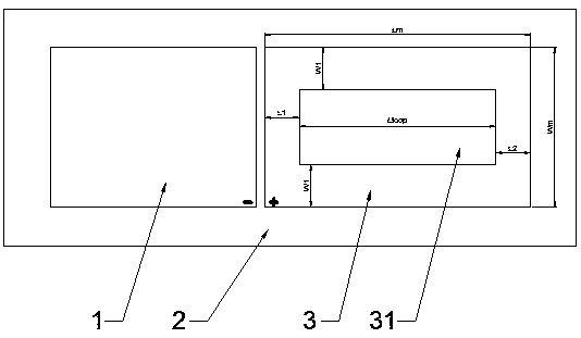
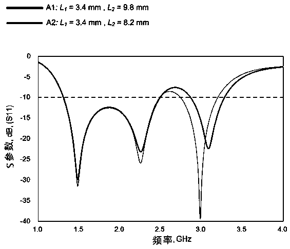
[0020] Antenna A1 : L1=3.4mm, L2=9.8mm, Antenna A2: L1=3.4mm, L2=8.2mm, figure 2 is the simulation result of antenna A1 and antenna A2, it can be seen that changing the length of L2 makes the cavity 31 L loop The length is reduced, and the feedback loss of the antenna, that is, the resonant frequency of the antenna is higher;

Embodiment 2

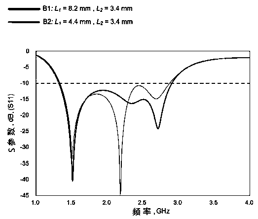
[0022] Antenna B1: L1=8.2mm, L2=3.4mm, Antenna B2: L1=4.4mm, L2=3.4mm, image 3 is the simulation result of antenna B1 and antenna B2, it can be seen that changing the length of L1 makes the cavity 31 L loop The length is different, the feedback loss of the antenna, that is, the resonance frequency is different, L loop The shorter the length, the higher the antenna frequency. According to this principle, broadband antennas of different lengths can be produced and applied to products that require different operating frequencies.

[0023] Table 1. Dimensions of antennas with different cavity lengths

[0024] antenna

[0025] Figure 4 are the test results of antennas A1, A2, B1, and B2. It can be seen that the loop antenna of the present invention can obtain different operating frequencies by adjusting the lengths of L1 and L2 to meet the needs of different antenna products. In addition, due to 2.6-3.3 There is no LTE spectrum in GHz, but the present invention can...


PUM


Abstract

The invention discloses a planar loop antenna. The planar loop antenna comprises a PCB, a ground plane and a plane antenna, wherein the ground plane and the plane antenna are fixed on the PCB; and a rectangular cavity is arranged in the middle of the plane antenna. The invention furthermore discloses an application and application method of the antenna. According to the loop antenna, the antenna can obtain different working frequencies through adjusting the lengths of L1 and L2, so as to satisfy the using of different antenna products; and in addition, the loop antenna can support spectrum patterns within 1.5 to 2.6 GHz through adjusting L1 and L2, and also can support higher LTE spectrums of 3.3 to 3.9 GHz.

Description

technical field [0001] The invention relates to the technical field of communication, in particular to a planar loop antenna, an application of the antenna and an application method. Background technique [0002] The Internet of Things (IoT) refers to the interconnection and exchange of data between devices / sensors. Currently, with the explosive growth of IoT technology, more and more practical applications can be found in many fields, including security, asset tracking, agriculture, smart metering, smart city and smart home, etc. IoT applications have specific requirements such as long distances, low data rates, low energy consumption and cost-effectiveness. Widely used short-range radio technologies (eg, ZigBee, Bluetooth) are not suitable for scenarios requiring long-distance transmission. Solutions based on cellular communication (e.g., 2G, 3G, and 4G) can provide greater coverage, but they consume too much device energy. [0003] Therefore, the current solution is to...

Claims


Application Information

Patent Timeline
Patent Type & Authority Applications(China)
IPC IPC(8): H01Q1/38H01Q1/48H01Q7/00H01Q5/10H01Q5/20H01Q5/307
CPCH01Q1/38H01Q1/48H01Q5/10H01Q5/20H01Q5/307H01Q7/00
Inventor 袁信明蒙伟贤胡家明
Owner INNOVATION SOUND TECH
Learn More