Switching method for neutral point grounding mode

A technology of neutral point grounding and neutral point ungrounding, applied in electrical components, information technology support systems, multi-phase network asymmetry measurement, etc. Low-voltage network counterattack and other problems, to reduce search work, save manpower and material resources, and quickly restore power supply

Inactive Publication Date: 2019-02-15
张安斌
View PDF5 Cites 5 Cited by
  • Summary
  • Abstract
  • Description
  • Claims
  • Application Information

AI Technical Summary

Problems solved by technology

The advantage of the neutral point effective grounding method is that its internal overvoltage is low, the fault point is easy to locate, and the fault line can be quickly removed; its disadvantage is that because of the rapid removal of the fault line, the intermittent power supply leads to a high tripping rate and low power supply reliability. ; Moreover, the ground current is large, the ground potential rises higher, and the contact voltage and step voltage are increased; the interference to the information system is increased; the low-voltage network counterattack is increased
The advantages of non-effective neutral grounding are: single-phase grounding fault steady-state power frequency current is small; lightning insulation flashover instantaneous fault can be automatically cleared without tripping; single-phase grounding operation can improve the uninterrupted power supply of the grid and improve the reliability of power supply The grounding current is small, which reduces the rise of the ground potential, reduces the step voltage, reduces the interference to the information system, and reduces the counterattack to the low-voltage network, etc.; the disadvantage is: the internal overvoltage is high, and the weak The probability of insulation breakdown is high; the fault point is difficult to locate, and there is no line selection device that can select lines 100% accurately

Method used


Image

  • Switching method for neutral point grounding mode
  • Switching method for neutral point grounding mode
  • Switching method for neutral point grounding mode

Examples


Embodiment Construction

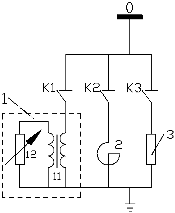
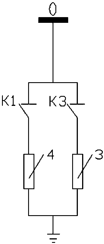
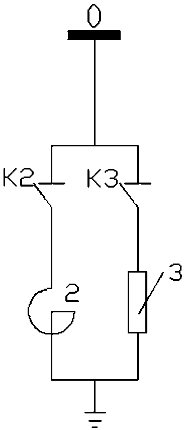
[0026] The switching method of the neutral point grounding mode in this embodiment is to set a controllable impedance between the neutral point of the power grid and the ground, and the controllable impedance is switched to different resistance values ​​when the power grid is in normal operation and when a single-phase grounding fault occurs.

[0027] The neutral point grounding method involves the safety, reliability and economy of the power grid; at the same time, it directly affects the selection of insulation level of system equipment, overvoltage level, relay protection mode and communication interference. At present, the neutral point grounding method of a power grid has only one grounding method, and the neutral point grounding method is the same regardless of normal operation or fault.

[0028] Different neutral point grounding methods have their own advantages and disadvantages, and the advantages of the high-current grounding method are the disadvantages of the low-cu...


PUM


Abstract

The invention discloses a switching method for a neutral point grounding mode. Controllable impedance is arranged between a neutral point of a power grid and ground and is switched to different resistances during normal running of the power grid and in a single-phase grounding fault. The switching method comprises the steps of arranging that the neutral point is not connected with ground during normal running, and switching to the situation that a neutral point arc elimination coil is connected with the ground or a high-value resistor is connected with the ground when the single-phase grounding fault occurs; and switching to the situation that the neutral point is not connected with the ground if the fault disappears within set time, switching to the situation that a medium-value resistorof the neutral point is connected with the ground if the fault does not disappear, and switching to the running mode that the neutral point is not connected with the ground after the single-phase grounding fault is eliminated. The advantages of various grounding modes are compatible, and the high power supply reliability of a power grid is improved.

Description

technical field [0001] The invention relates to electric power equipment, more specifically, it provides a neutral point grounding mode switching method for a medium-voltage power grid, and realizes the mutual conversion of two or more neutral point grounding modes in one power grid and single-phase grounding fault location. Background technique [0002] The electrical connection between the neutral point of the three-phase AC power system and the earth is called the grid neutral point grounding method. The neutral point grounding method involves the safety, reliability and economy of the power grid; at the same time, it directly affects the selection of insulation level of system equipment, overvoltage level, relay protection mode, communication interference, etc. Generally speaking, the neutral point grounding method of the power grid is also the neutral point grounding method of the voltage transformers at all levels in the substation. [0003] The neutral point effectiv...

Claims


Application Information

Patent Timeline
Patent Type & Authority Applications(China)
IPC IPC(8): H02H7/26G01R29/16G01R31/08
CPCG01R29/16G01R31/08H02H7/262H02H7/263Y04S10/52
Inventor 张安斌
Owner 张安斌
Why Eureka
Try Eureka