Dual-mode switching frequency control system

A switching frequency and control system technology, applied in control/regulation systems, output power conversion devices, DC power input conversion to DC power output, etc., can solve the problem of difficult to meet various application scenarios, single mode of switching frequency control system, etc. problem, to achieve the effect of solving the switching frequency single-mode control and establishing a fast speed

Pending Publication Date: 2022-01-28
THREE PEAK SEMICON (SHANGHAI) CO LTD
View PDF0 Cites 0 Cited by
  • Summary
  • Abstract
  • Description
  • Claims
  • Application Information

AI Technical Summary

Problems solved by technology

The switching frequency control system in the existing switching power supply has a

Method used


Image

  • Dual-mode switching frequency control system
  • Dual-mode switching frequency control system
  • Dual-mode switching frequency control system

Examples


Embodiment 1

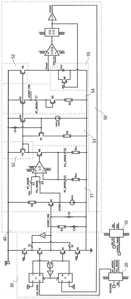
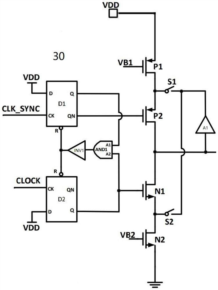
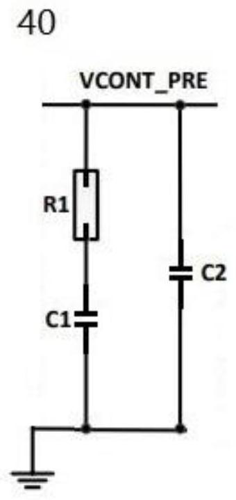
[0055] Such as figure 1 As shown, a dual-mode switching frequency control system includes: an enabling circuit 10 , a mode determination circuit 20 , a phase detector 30 , a loop filter 40 and an oscillator 50 .

[0056] The enabling circuit 10 outputs an enabling signal EN according to the input signal EN_CK, and the enabling signal EN is an enabling signal of the entire switching frequency control system. The input signal EN_CK is equal to the enable signal EN. When the two are "1", the entire switching frequency control system works normally. When the enable signal EN is "0", the entire switching frequency control system does not work. Therefore, the following analysis is to make The premise is that the enable signal EN is "1". The input signal FORCE_FMIN is used to indicate whether the system is operating at the lowest frequency and at the same time the enabling signal EN1 is output through the enabling circuit 10. When the input signal FORCE_FMIN is "1", the enabling sig...

Embodiment 2

[0088] In order to solve the problem in Embodiment 1 that the system will have abnormal behavior when it just exits the lowest frequency working state, such as Figure 6 As shown, this embodiment provides another dual-mode switching frequency control system, including: a first phase-locked loop and a second phase-locked loop. The first phase-locked loop includes a phase detector 100, a loop filter 200, and a first oscillator 300; the second oscillator 400 and the first oscillator 300 can be switched to form a second phase-locked loop, that is, the first phase-locked loop The phase loop and the second phase locked loop share the phase detector 100 and the loop filter 200 .

[0089] The dual-mode switching frequency control system also includes a first selector and a second selector, the I0 input and output of the first selector are connected to the first oscillator 300, and the I1 input of the first selector is connected to the second oscillator 400 . The I0 input terminal of...


PUM


Abstract

The invention discloses a dual-mode switching frequency control system. The dual-mode switching frequency control system comprises an oscillator, a phase discriminator and a loop filter. In an RT mode, the oscillator can output a clock signal with a preset frequency; in a PLL mode, the oscillator can output a clock signal synchronized with an external clock signal; and in the RT mode and/or the PLL mode, when the oscillator works in a lowest-frequency working state, a clock signal with the lowest frequency can be output. According to the dual-mode switching frequency control system provided by the embodiment of the invention, mutual switching between the RT mode and the PLL mode can be realized, the establishment speed of the phase-locked loop is high, the establishment time required when the frequency of the clock signal output by the oscillator is synchronized to the frequency of the external clock signal during switching between the two modes can be shortened, and the problem of single-mode control of switching frequency in a common switching power supply is effectively solved.

Description

technical field [0001] The invention relates to the technical field of integrated circuits, in particular to a dual-mode switching frequency control system. Background technique [0002] Switching power supply is widely used in the field of integrated circuits. Switching power supply is a high-frequency power conversion device that converts a level of voltage into the voltage or current required by the user through different forms of architecture. The switching frequency control system in the existing switching power supply has a single mode, which is difficult to meet the needs of various application scenarios. [0003] The information disclosed in this Background section is only for enhancing the understanding of the general background of the present invention and should not be taken as an acknowledgment or any form of suggestion that the information constitutes the prior art that is already known to those skilled in the art. Contents of the invention [0004] The objec...

Claims


Application Information

Patent Timeline
IPC IPC(8): H02M3/156H02M3/158H02M1/44
CPCH02M3/156H02M3/158H02M1/44
Inventor 薛尚嵘冯翰雪李冬超
Owner THREE PEAK SEMICON (SHANGHAI) CO LTD
Why Eureka
Try Eureka