Novel hay mower

A lawn mower, a new type of technology, applied in the direction of harvesters, cutters, agricultural machinery and implements, etc., can solve the problem of not being able to cut different types of weeds

Active Publication Date: 2019-02-19
滨州高新区国有资本投资运营有限公司
View PDF6 Cites 2 Cited by
  • Summary
  • Abstract
  • Description
  • Claims
  • Application Information

AI Technical Summary

Problems solved by technology

[0002] For example, the patent No. is CN201711039360.2, a new type of lawn mower, including a lawn mower body, the lawn mower body is provided with a bracket, both sides below the bracket are provided with a walking mechanism, the inside of the bracket is provided with a cutter head, and the cutter head is equipped with a first A motor, blades are installed on the output shaft of the first motor, a chassis is provided on one side of the cutter head, a second motor is installed on the chassis, and a weeding wheel is installed on the output shaft of the second motor; the inner wall of the cutter head and the inner wall of the chassis are equipped with The water spray nozzle is connected with a hose; the lawn mower body is provided with an infrared sensor, the infrared sensor is connected with a controller, the controller is located inside the motor cover, the controller is connected with a direction device, and the controllers are respectively It is connected with the walking mechanism, the first motor, and the second motor, but the disadvantage of this invention is that it can only cut grass at a fixed speed, and cannot cut for different types of weeds

Method used


Image

  • Novel hay mower
  • Novel hay mower
  • Novel hay mower

Examples


specific Embodiment approach 1

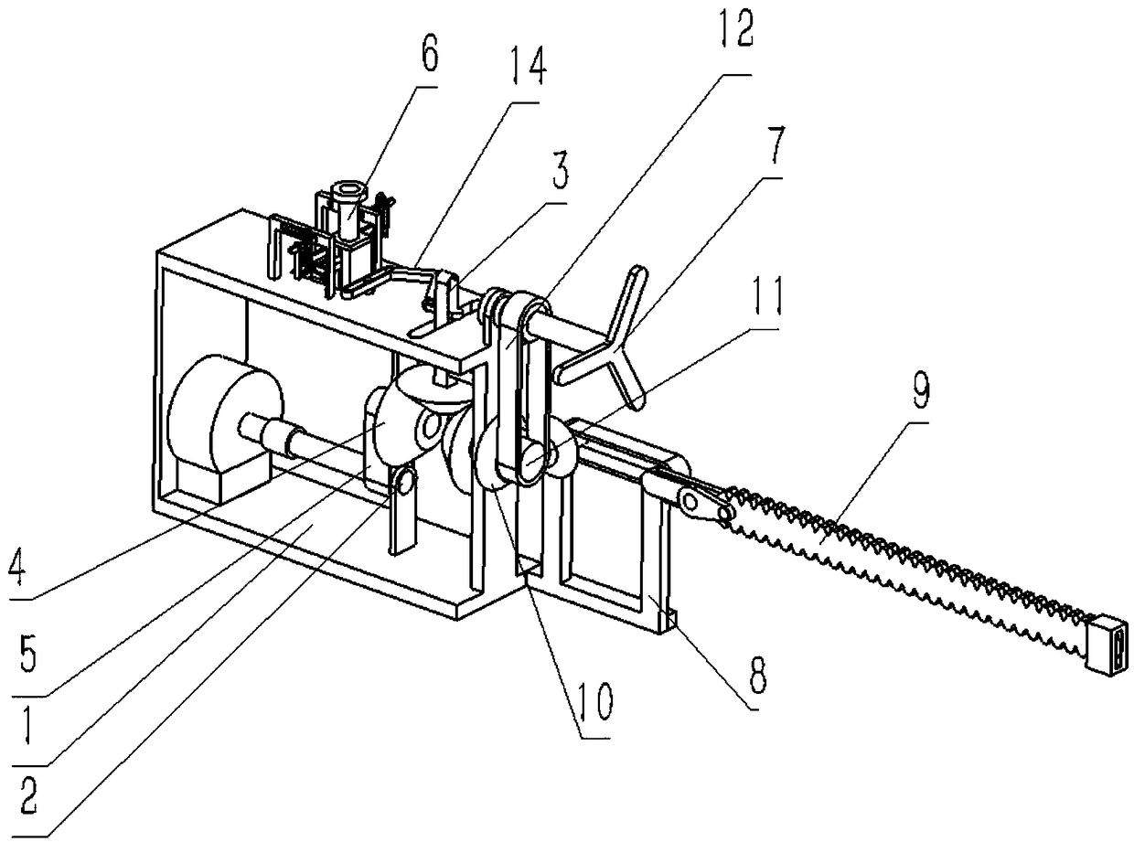
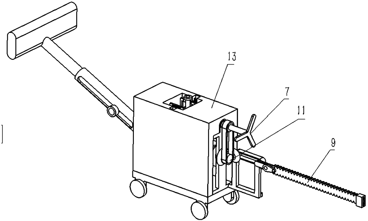
[0039] Combine below Figure 1-16 Describe this embodiment, a new type of lawn mower, including a power frame 1, a sliding hole coupling 2, a fixed outer frame 3, a sliding rotating rod 4, a transmission belt 5, a switching push combination 6, a blowing combination 7, a transmission fixing Frame 8, tooth base 9, transmission bevel gear 10, transmission shaft assembly 11, synchronous belt I 12, manual push rod 13 and driving rod assembly 14, characterized in that: the power frame 1 is fixedly connected in the fixed outer frame 3 At the middle end of the end face, the sliding hole coupling 2 is rotatably connected to the right end of the fixed outer frame 3, the sliding rotating rod 4 is slidingly connected to the upper end of the power frame 1, and the right end of the sliding rotating rod 4 is slidingly connected to the bottom of the sliding hole coupling 2. The left end, the right end of the sliding hole coupling 2 is fixedly connected to the left end of the running belt oute...

specific Embodiment approach 2

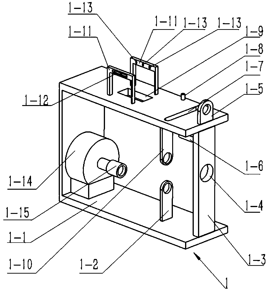
[0040] Combine below Figure 1-16 Describe this embodiment. This embodiment will further explain Embodiment 1. The power frame 1 includes a power frame bottom plate 1-1, an inner and lower hinge plate 1-2, a front hinge plate 1-3, and a middle end turning hole 1. -4. Front upper hinged plate 1-5, inner sliding column 1-6, upper rectangular sliding hole 1-7, upper hinged column 1-8, upper middle sliding hole 1-9, inner upper hinged plate 1-10, two side wall sliding rods 1-11, two concave grooves 1-12, multiple card slots 1-13, input motor 1-14 and coupling 1-15, inner lower hinge plate 1 -2 is fixedly connected to the middle end of the lower end surface of the inner wall of the power frame bottom plate 1-1, the front hinge plate 1-3 is fixedly connected to the front end surface of the power frame bottom plate 1-1, and the middle end turning hole 1-4 is set at the front hinge The middle end of the plate 1-3, the front upper hinge plate 1-5 is fixedly connected to the front end ...

specific Embodiment approach 3

[0042] Combine below Figure 1-16 Describe this embodiment, this embodiment will further explain the second embodiment, the sliding hole coupling 2 includes a sliding hole coupling body 2-1 and an input drive pulley 2-2, and the input drive pulley 2-2 is evenly arranged On the inner wall of the sliding hole coupling body 2-1, the inner end of the sliding hole coupling body 2-1 is hollowed out, and the left end of the upper rotating shaft 4-6 is slidably connected to the right end of the sliding hole coupling body 2-1 , the sliding hole coupling body 2-1 is fixedly connected in the coupling 1-15, and the front end of the sliding hole coupling body 2-1 is rotatably connected to the inner lower hinge plate 1-2;

[0043] The sliding hole coupling body 2-1 can conveniently set the input driving pulley 2-2; the inner lower hinge plate 1-2 can be fixedly connected with the sliding hole coupling body 2-1 conveniently.


PUM


Abstract

The invention relates to a life tool, in particular to a novel hay mower. The speed of the hay mower can be adjusted so that the hay mower can cut kinds of forage conveniently; meanwhile, air blower equipment is arranged; the cut forage is convenient to clear; the speed of the air blower equipment can be adjusted, so that working efficiency is improved; the air blower equipment comprises a power frame, a sliding hole coupler, a fixed outer frame, a sliding rotating rod, a drive belt, a switch pressing combination, an air blowing combination body, a drive fixed frame, a tooth saw, a drive conical tooth, a drive shaft combination body, a first synchronous belt I, a manual pushing rod and a poking rod combination body, and a bottom plate can be conveniently and fixedly connected with a support rod; through a right side rotating hole, rotating connection of an upper side rotating shaft can be convenient; through a left side rotating hole, sliding connection of a sliding hole coupler body can be convenient; a front side hinging terminal can allow a door-type pressing rod to be hinged conveniently; a rear side hinging terminal can allow a connecting rod to be hinged conveniently; througha manual rotating rod, the door-type pressing rod and the connecting rod can be conveniently connected.

Description

technical field [0001] The invention relates to a living tool, more specifically a novel lawnmower. Background technique [0002] For example, the patent No. is CN201711039360.2, a new type of lawn mower, including a lawn mower body, the lawn mower body is provided with a bracket, both sides below the bracket are provided with a walking mechanism, the inside of the bracket is provided with a cutter head, and the cutter head is equipped with a first A motor, blades are installed on the output shaft of the first motor, a chassis is provided on one side of the cutter head, a second motor is installed on the chassis, and a weeding wheel is installed on the output shaft of the second motor; the inner wall of the cutter head and the inner wall of the chassis are equipped with The water spray nozzle is connected with a hose; the lawn mower body is provided with an infrared sensor, the infrared sensor is connected with a controller, the controller is located inside the motor cover, ...

Claims


Application Information

Patent Timeline
Patent Type & Authority Applications(China)
IPC IPC(8): A01D34/10A01D34/125A01D34/40
CPCA01D34/10A01D34/125A01D34/40
Inventor 周喜荣
Owner 滨州高新区国有资本投资运营有限公司
Why Eureka
Try Eureka