Dust collector

A technology for vacuum cleaners and suction pipes, which is applied in the direction of vacuum cleaners, suction nozzles, suction hoses, etc., which can solve the problems of poor filtration efficiency and filtration effect, and achieve simple and practical structure, increased dust suction wind power, and convenient assembly and disassembly quick effect

Pending Publication Date: 2019-02-19
NINGBO DECHANG ELECTRICAL MACHINERY MFG CO LTD
View PDF7 Cites 2 Cited by
  • Summary
  • Abstract
  • Description
  • Claims
  • Application Information

AI Technical Summary

Problems solved by technology

[0003] The purpose of the present invention is to overcome the disadvantages of poor filtration efficiency and filtering effect of the filter device in the current vacuum cleaner, and provide a vacuum cleaner with better filtration efficiency and filtering effect of the filter device

Method used


Image

  • Dust collector
  • Dust collector
  • Dust collector

Examples


Embodiment Construction

[0022] The present invention will be further described below in conjunction with the accompanying drawings.

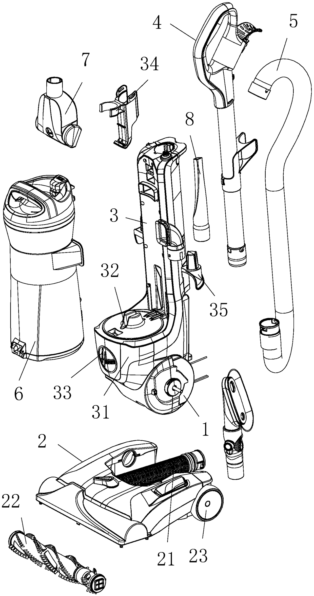
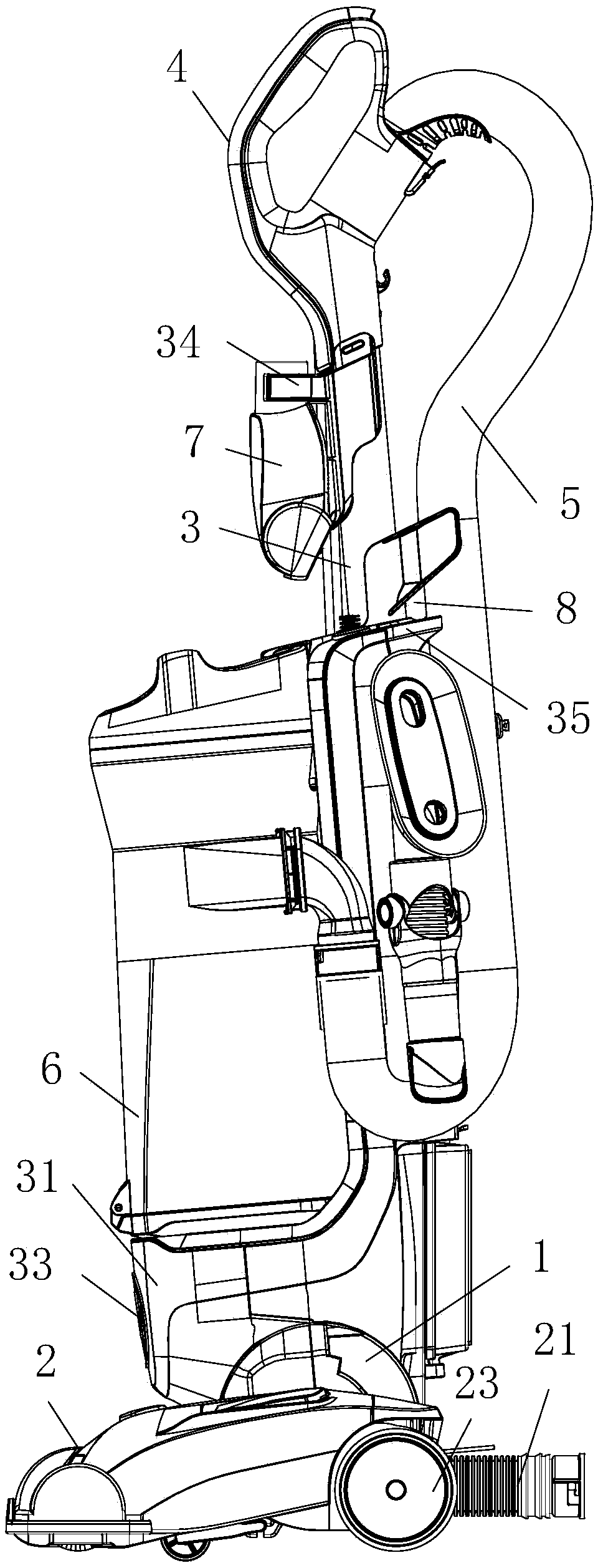
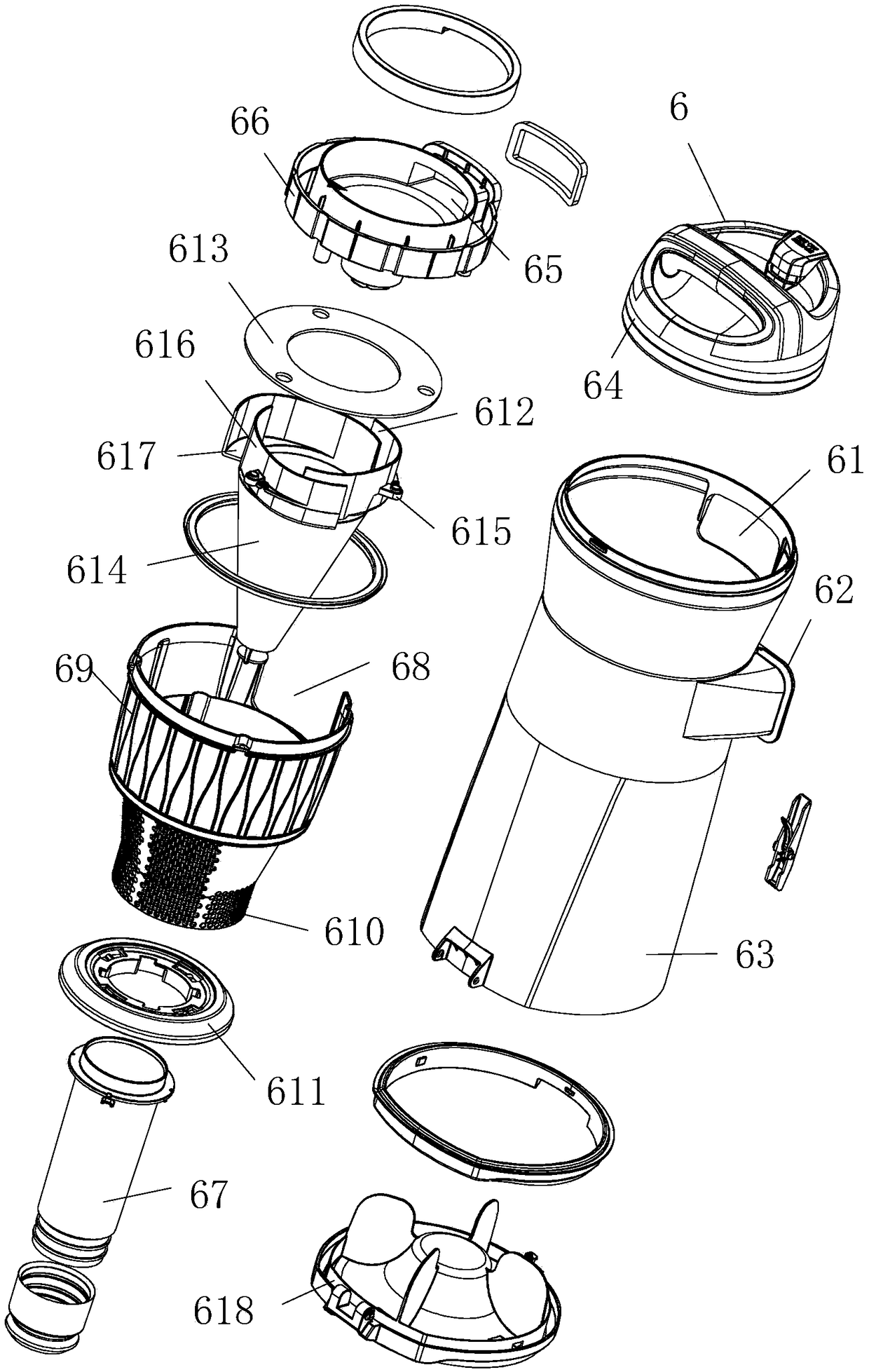
[0023] as attached figure 1 to attach Figure 6Shown: a vacuum cleaner, comprising: a ground mopping device 2 provided with an air extraction pipe 21, a rolling brush 22 and a roller 23, an air extraction fan 1 connected to the upper end of the floor mopping device 2, and a suction fan 1 connected to the lower end of the mop device 2; The fuselage 3 of the dust collector 31 is located on one side of the fuselage 3 and is provided with a dust suction pipe 5 with a handle 4, several dust suction heads, and a dust cup filter device 6 located at the upper end of the dust collector 31; The filtering device 6 comprises: a casing 63 with a suction port 61 communicated with the suction end of the suction fan 1 and a suction port 62 located at the lower side of the suction port 61 and connected with the other end of the suction pipe 5 around the side, and the housing 63 The l...


PUM


Abstract

The invention relates to a dust collector, which comprises a mopping device provided with a suction pipe, a roller brush and a roller, a suction fan connected with the upper end of the mopping device,a dust collector body, the lower end of which is connected with the suction fan, a dust suction pipe arranged on one side of the body and provided with a holding rod, and a plurality of dust suctionheads, a dust cup filter device arranged at the upper end of the dust collector; the dust cup filter device includes: a side body, which is provided with a suction port connected with the suction endof the suction fan and a shell of the suction port, which is arranged at the lower end of the suction port and communicated with the other end of the suction pipe, an upper cover connected with the upper end of the shell, a dust cup cover which is arranged in the shell and is communicated with a suction hole communicated with the suction port, a filter, separator and dust collecting pipe arrangedat the lower side of the dust cup cover and a bottom cover sleeved outside the lower end of the dust collecting pipe and detachably connected with the shell. The lower end of the dust collecting pipeis inserted into a dust collecting inlet arranged in the upper end of the dust collector; one end of the suction pipe is detachably connected with the dust collecting pipe, or one end of the dust collecting pipe is detachably connected with a dust collecting head.

Description

technical field [0001] The invention relates to the field of household appliances, in particular to a vacuum cleaner. Background technique [0002] The structure of the vacuum cleaner can be obtained from a multi-functional household vacuum cleaner disclosed in the utility model of the Chinese patent application number CN201721214456.3; the traditional vacuum cleaner has the disadvantages of poor filtration efficiency and filtering effect of the filter device, therefore, a filter is designed The filter efficiency of device and the better vacuum cleaner of filter effect become the problem demanding prompt solution. Contents of the invention [0003] The purpose of the present invention is to overcome the disadvantages of poor filtering efficiency and filtering effect of the filtering device in the current vacuum cleaner, and provide a vacuum cleaner with better filtering efficiency and filtering effect of the filtering device. [0004] Concrete technical scheme of the pres...

Claims


Application Information

Patent Timeline
Patent Type & Authority Applications(China)
IPC IPC(8): A47L5/12A47L9/04A47L9/24A47L9/32
CPCA47L5/12A47L9/04A47L9/244A47L9/322
Inventor 李涛姜义庭徐能军
Owner NINGBO DECHANG ELECTRICAL MACHINERY MFG CO LTD
Why Eureka
Try Eureka