A capsule locking device for a fully automatic capsule filling machine

A technology of a locking device and a filling machine, which is applied in the directions of capsule delivery, pharmaceutical formulation, and drug delivery, can solve the problems of easy errors in the adjustment process, lowering the quality of capsule locking, and different degrees of capsule locking, so as to avoid errors. , Simplify the process of adjusting the locking thimble and reduce the effect of the defective rate

Active Publication Date: 2020-11-13
聊城开发区东山物业管理有限公司
View PDF5 Cites 0 Cited by
  • Summary
  • Abstract
  • Description
  • Claims
  • Application Information

AI Technical Summary

Problems solved by technology

[0003] 1. The locking plate of the existing capsule locking device is equipped with a plurality of locking thimbles through the limit nut and the fastening nut. The stroke of the locking thimble cannot be changed due to the limitation of the locking plate. At the same time, each locking thimble needs to be adjusted individually. The adjustment process is very cumbersome, time-consuming and laborious, and errors are prone to occur during the adjustment process, which makes the distance between the top of different locking thimbles and the locking plate different, resulting in different locking thimbles. The strokes implemented for the corresponding capsules are different, resulting in different locking degrees of different capsules, and the defective rate is relatively high
[0004] 2. The top of the locking thimble is flat and the bottom of the capsule is hemispherical. The contact area between the locking thimble and the bottom of the capsule is very small. When the locking thimble contacts the capsule, the bottom of the capsule will be affected by a The large instantaneous pressure easily deforms the bottom of the capsule body and reduces the quality of capsule closure

Method used


Image

  • A capsule locking device for a fully automatic capsule filling machine
  • A capsule locking device for a fully automatic capsule filling machine
  • A capsule locking device for a fully automatic capsule filling machine

Examples


Embodiment Construction

[0020] The following will clearly and completely describe the technical solutions in the embodiments of the present invention with reference to the accompanying drawings in the embodiments of the present invention. Obviously, the described embodiments are only some, not all, embodiments of the present invention. Based on the embodiments of the present invention, all other embodiments obtained by persons of ordinary skill in the art without making creative efforts belong to the protection scope of the present invention.

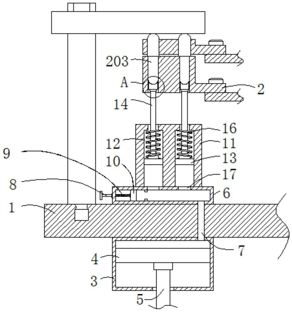
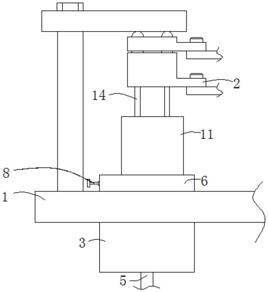
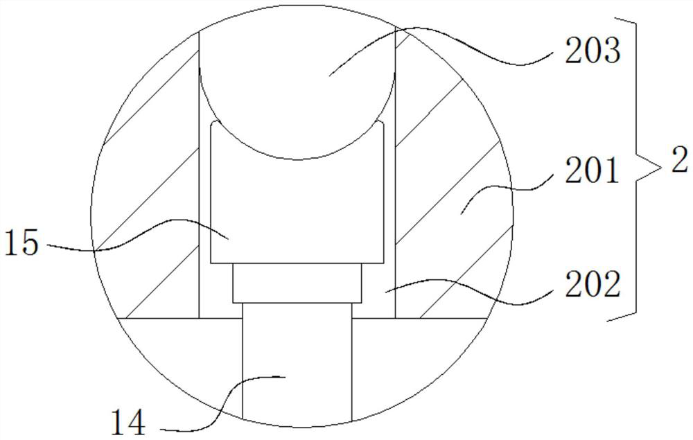
[0021] see Figure 1-4 , a capsule locking device for a fully automatic capsule filling machine, comprising a support platform 1 and a lower mold 2, an air pressure box 3 is fixedly installed on the bottom surface of the support platform 1, and a power piston 4 is arranged inside the air pressure box 3, The power piston 4 is compatible with the air pressure box 3, the bottom surface of the power piston 4 is fixedly equipped with a transmission rod 5, the botto...


PUM


Abstract

The invention relates to the technical field of intelligent manufacturing and discloses a capsule locking device for a fully-automatic capsule filling machine. The capsule locking device for the fully-automatic capsule filling machine comprises a support platform and a lower mold, the bottom surface of the support platform is fixedly provided with an air pressure tank, the inside of the air pressure tank is provided with a power piston which is matched with the air pressure tank, and the bottom surface of the power piston is fixedly provided with a transmission rod; a user can control the position of a power regulating piston to control the air pressure inside a pressure balancing tank, accordingly to control the maximum value of the air pressure inside the pressure balancing tank, furtherto control the pneumatic thrust born by a driven piston and finally to achieve simultaneously adjustment of the pushing stroke of locking centers, thereby meeting the requirements of locking processes of capsules of different specifications on the stroke of the locking centers. Compared with the prior art, the capsule locking device for the fully-automatic capsule filling machine is simple in adjustment, saves time and labor, avoids the problems of errors caused by one-by-one adjustment of the locking centers, ensures identical locking degree of all capsules and reduces the defect rate of products.

Description

technical field [0001] The invention relates to the technical field of intelligent manufacturing, in particular to a capsule locking device for a fully automatic capsule filling machine. Background technique [0002] The production of capsules by the automatic capsule filling machine generally needs to go through the process of separating the capsule body and the capsule cap - metering and filling - capsule waste - capsule locking - finished product release - powder cleaning, etc. The capsule locking process is installed on the The mold on the turntable moves to the capsule locking station, and then the capsule body and capsule cap inside the mold are locked by the capsule locking device. The existing capsule locking device is rotated by the motor with the eccentric wheel, and the eccentric wheel is driven by the transmission rod. As the locking plate moves up and down, the rows of locking thimbles on the top surface of the locking plate move up and down to lock the capsule....

Claims


Application Information

Patent Timeline
Patent Type & Authority Patents(China)
IPC IPC(8): A61J3/07
CPCA61J3/074
Inventor 不公告发明人
Owner 聊城开发区东山物业管理有限公司
Why Eureka
Try Eureka