Compact charging and baiting material feeding mechanism of bonder

A feeding mechanism, compact technology, applied in the field of bonding machine compact loading and unloading feeding mechanism, can solve the problems of large space size, large equipment footprint, etc., to achieve reduced size and space, low cost, and meet the travel schedule required effect

Inactive Publication Date: 2010-02-24
THE 45TH RES INST OF CETC
View PDF4 Cites 0 Cited by
  • Summary
  • Abstract
  • Description
  • Claims
  • Application Information

AI Technical Summary

Problems solved by technology

In the design process, the stroke and space are difficult to reconcile contradictions, and the common loading and unloading mechanism design has a large space size, and the stroke causes a large equipment footprint

Method used


Image

  • Compact charging and baiting material feeding mechanism of bonder

Examples


Embodiment Construction

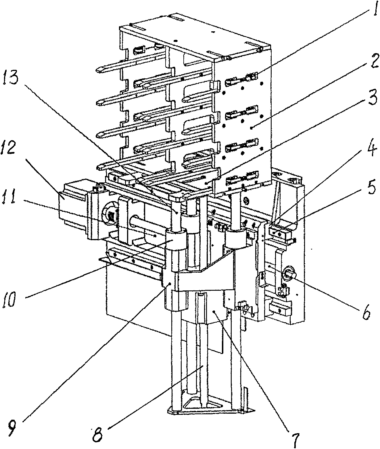
[0011] The present invention will be described in further detail below in conjunction with embodiment accompanying drawing:

[0012] Referring to the accompanying drawings, the present invention is used for a loading and unloading feeding mechanism on a fully automatic bonding machine. Guide rail 5 is installed on the base 11, and side platform 9 is installed on the slide block 4 that cooperates with guide rail 5, by guide rail slide block, side platform and feeding mechanism can compactly move horizontally. The first stepping motor 12 drives and controls the horizontal movement of the feeding unit 3 through the coupling and the first lead screw 6 . Three guide rods 13 are installed on the side platform 9 to guide the feeding unit. The power output shaft of the second stepper motor 7 is connected with the second lead screw 8 to directly drive and control the up and down movement of the feeding unit 3 . The distance between the feeding unit 3 and the side wall 2 can be adjuste...


PUM


Abstract

The invention relates to a wire bonder compact loading and unloading delivery gear which is suitable for a metal wire bonder, especially for production equipment of a semiconductor device. The invention comprises a base, a side platform and a feeding unit. The invention is characterized in that the base is fixed with a lead rail along the landscape orientation; the side platform is fixed with a slide rod which is mutually matched with the lead rail. A nut and a screw mandrel rotary actuator which are driven by a stepping motor are arranged between the side platform and the base along the landscape orientation; the side platform is provided with a guide sleeve along the portrait; the feeding unit is fixed with the guide rod which is matched with the guide sleeve, a nut and a screw mandrel rotary actuator which are driven by a stepping motor are arranged between the feeding unit and the side platform along the portrait. As the delivery gear of the invention adopts the unique constructionand the integration casting, the size space of the whole machine is obviously reduced, at the same time, the travel requirements can be satisfied, the design is easy to maintain, and the delivery gear has the advantages of simple structure, long service life, low cost, and being easy to control.

Description

technical field [0001] The invention relates to a compact loading and unloading feeding mechanism of a bonding machine, which is suitable for metal wire bonding machines, especially for production equipment of semiconductor devices. Background technique [0002] Fully automatic wire bonding machine is a key semiconductor equipment that connects chip pads and package pins with metal wires. In the process of automatic LED production, it is necessary to adapt to the packaging of the fully automatic LED wire bonding machine in the factory, and the loading and unloading and feeding system of the bracket must be automatically completed by the equipment. When the space structure of the equipment is limited and different support specifications are required, compact upper and lower feeding mechanisms and adjustable silos are very necessary. In the design process, the stroke and space are difficult to reconcile contradictions, and the common loading and unloading mechanism design has...

Claims


Application Information

Patent Timeline
Patent Type & Authority Patents(China)
IPC IPC(8): H01L21/677H01L21/60H01L33/00
CPCH01L2224/78
Inventor 张续业潘峰
Owner THE 45TH RES INST OF CETC
Why Eureka
Try Eureka